
Spindle tool handle clamping mechanism with end face pollutant-hiding function

A technology of clamping mechanism and tool holder, applied in the direction of clamping, metal processing mechanical parts, supports, etc., can solve the problems of affecting tightness, large contact area, reduction of spindle machining accuracy, etc., to improve cleanliness and ensure machining accuracy. , the effect of meeting application requirements

Pending Publication Date: 2020-06-05
深圳市爱贝科精密工业股份有限公司
View PDF0 Cites 0 Cited by
  • Summary
  • Abstract
  • Description
  • Claims
  • Application Information

AI Technical Summary

Problems solved by technology

[0002] The front end of the rotor of the spindle equipment is generally used to install the tool handle. During the process of unloading and changing the tool, the joint between the rear end of the tool handle and the front end of the rotor is easy to hide dust and waste. If these dust and waste cannot be removed, It will directly affect the machining accuracy of the spindle. In the prior art, in order to clean dirt such as dust and waste chips, some spindles will have front-end air holes that can blow out airflow on the front face of the rotor. Although this method can remove Part of the dirt, but some dirt will be hidden between the two air holes. When the tool holder is combined with the rotor, it will still affect the tightness between the two, resulting in a reduction in the machining accuracy of the spindle.
At the same time, the existing main shaft generally adopts the contact method between the end surface of the main rotor and the taper surface of the tool handle, and the contact area is relatively large.

Method used


Image

  • Spindle tool handle clamping mechanism with end face pollutant-hiding function
  • Spindle tool handle clamping mechanism with end face pollutant-hiding function
  • Spindle tool handle clamping mechanism with end face pollutant-hiding function

Examples


Embodiment Construction

[0013] The present invention will be described in more detail below in conjunction with the accompanying drawings and embodiments.

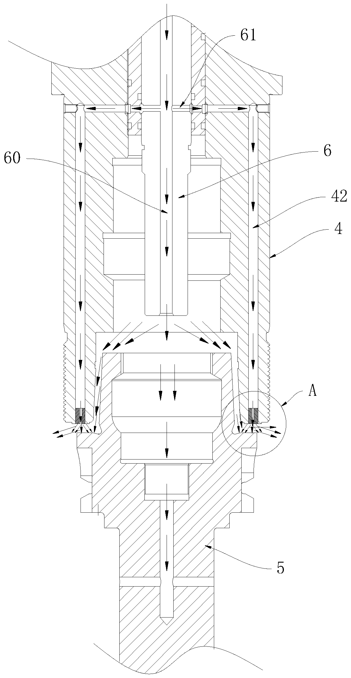
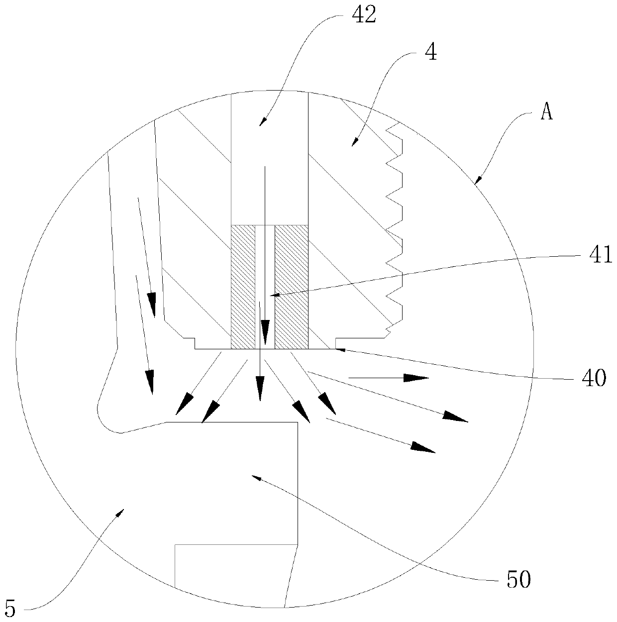
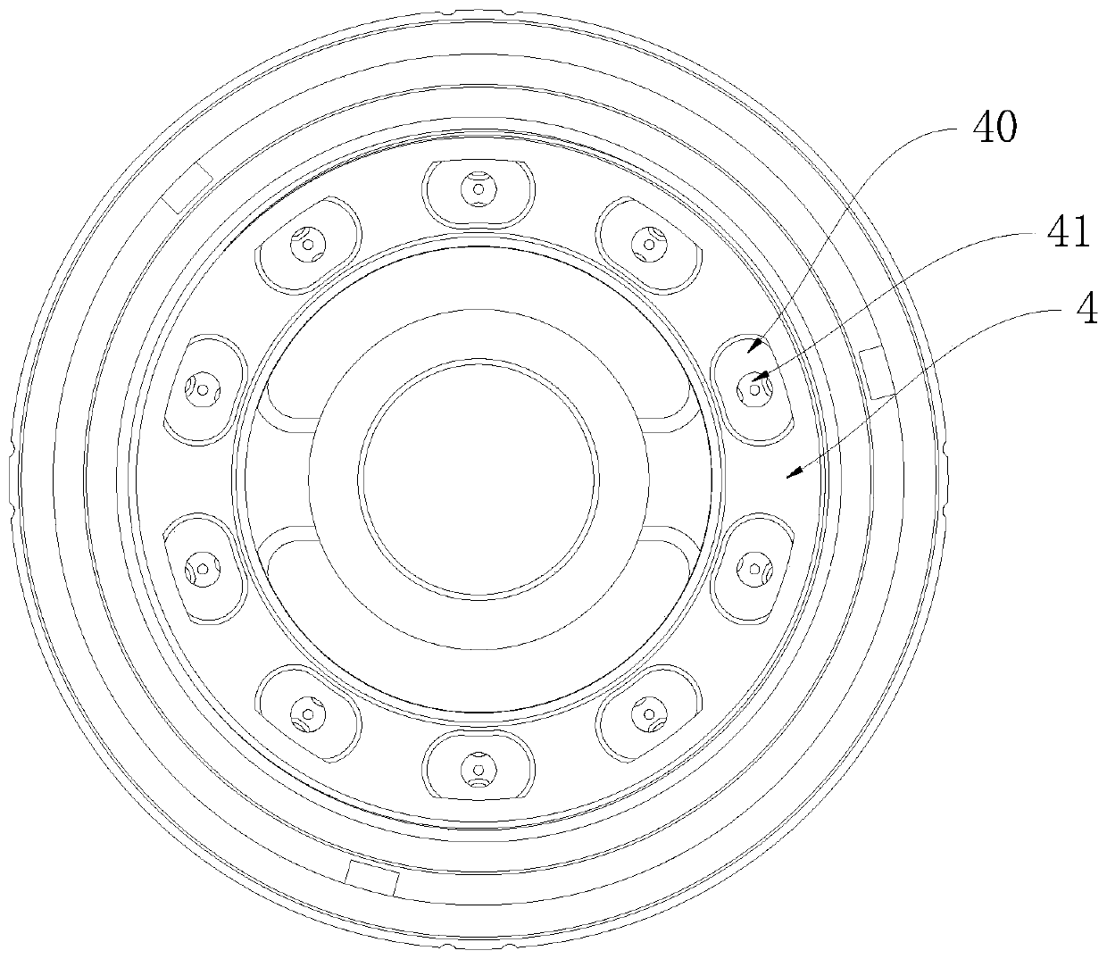
[0014] The invention discloses a clamping mechanism for a main shaft handle with dirt on the end surface, which combines Figure 1 to Figure 3 As shown, it includes a rotor 4 and a handle 5, the rear end of the handle 5 is inserted into the front opening of the rotor 4, the outer wall of the handle 5 is formed with an annular shoulder 50, so The annular shoulder 50 is aligned with the front end surface of the rotor 4, and the front end surface of the rotor 4 is formed with a plurality of protruding bosses 40, and a gap is provided between two adjacent bosses 40, The front end surface of the boss 40 is provided with a front end air hole 41, and a plurality of rotor air passages 42 for injecting compressed air are provided in the side wall of the rotor 4, and the rotor air passages 42 communicate with each other one by one. The front end air hole ...


PUM


Abstract

The invention discloses a spindle tool handle clamping mechanism with an end face pollutant-hiding function. The spindle tool handle clamping mechanism comprises a rotor and a tool handle, an annularshoulder is formed on the outer side wall of the tool handle, the annular shoulder is aligned with the front end face of the rotor, a plurality of bosses protruding forwards are formed on the front end face of the rotor, a gap is formed between every two adjacent bosses, front end air holes are formed in the front end faces of the bosses, a plurality of rotor air channels used for allowing compressed air to be injected are formed in the side wall of the rotor, the rotor air channels communicate with the front end air holes in a one-to-one correspondence mode, a pull rod is arranged in the rotor, a central air channel used for allowing compressed air to be injected is formed in the center of the pull rod, when the tool handle is disassembled and assembled, the front end face of the rotor and the annular shoulder are cleaned by means of airflow blown out of the front end air holes, and the rear end face of the tool handle and the gap between every two bosses are cleaned through airflow blown out of the central air channel. According to the spindle tool handle clamping mechanism with the end face pollutant-hiding function, a part of pollutants can be hidden temporarily, so that the tool handle is tightly combined with the rotor, and the pollutants are removed in time when the tool handle is disassembled and assembled.

Description

technical field [0001] The invention relates to an electric spindle, in particular to a spindle tool handle clamping mechanism with dirt on the end surface. Background technique [0002] The front end of the rotor of the spindle equipment is generally used to install the tool handle. During the process of unloading and changing the tool, the joint between the rear end of the tool handle and the front end of the rotor is easy to hide dust and waste. If these dust and waste cannot be removed, It will directly affect the machining accuracy of the spindle. In the prior art, in order to clean dirt such as dust and waste chips, some spindles will have front-end air holes that can blow out airflow on the front face of the rotor. Although this method can remove Part of the dirt, but some dirt will be hidden between the two air holes. When the tool holder is combined with the rotor, it will still affect the tightness between the two, resulting in a reduction in the machining accuracy...

Claims


Application Information

Patent Timeline
Patent Type & Authority Applications(China)
IPC IPC(8): B23Q3/12B23Q11/00
CPCB23Q3/12B23Q11/00
Inventor 农乃昌
Owner 深圳市爱贝科精密工业股份有限公司
Features
  • Generate Ideas
  • Intellectual Property
  • Life Sciences
  • Materials
  • Tech Scout
  • Unparalleled Data Quality
  • Higher Quality Content
  • 60% Fewer Hallucinations
Learn More