

Method for flattening and slitting pipe
A tube, leveling technology, applied in separation methods, chemical instruments and methods, dispersed particle separation, etc., to avoid rigid touch
- Summary
- Abstract
- Description
- Claims
- Application Information
AI Technical Summary
Problems solved by technology
Method used
Image

Examples
Embodiment 1
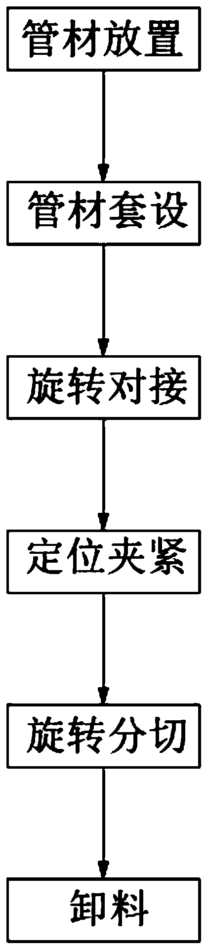
[0079] Such as figure 1 Shown, a kind of pipe flat cutting method comprises the following steps:
[0080] Step 1, placing the pipe material, placing the pipe material 10 to be cut on the material receiving seat 11 of the cutting processing table 1, and positioning by the material receiving groove 111 on the material receiving seat 11;
[0081] Step 2, the pipe is sleeved, the pushing mechanism 4 installed on the slitting and processing table 1 is activated, and the rotating mechanism 2 is pushed along the length direction of the material receiving seat 11. The pushing plate 22 on the rotating mechanism 2 and the pushing plate 22 placed on the The pipe material 10 on the material receiving seat 11 resists pushing, so that the pipe material 10 is sleeved on the cylindrical support cylinder group 31 in the cutting mechanism 3;
[0082] Step 3, rotating butt joint, synchronized with step 2, while the pusher plate 22 completes the casing work of the pipe 10, the rotating connector...
Embodiment 2
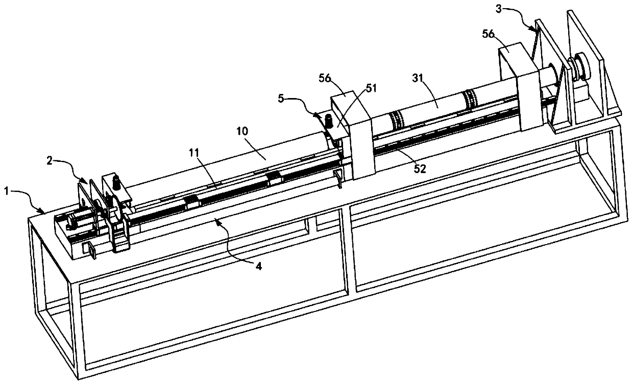
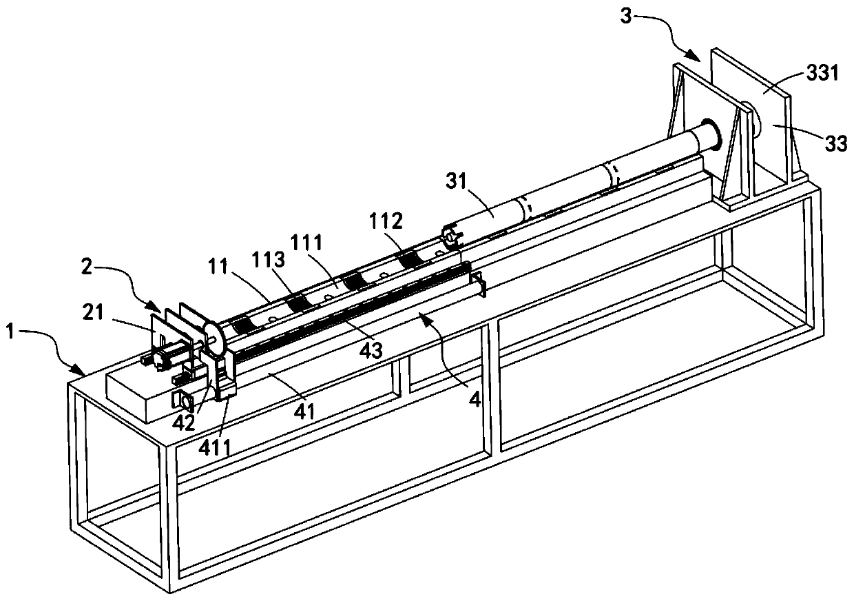
[0126] Such as Figures 2 to 8 Shown, a kind of pipe leveling and cutting device comprises:
[0127] The slitting processing table 1, the slitting processing table 1 is arranged horizontally, and a material receiving seat 11 is arranged on it, and the material receiving seat 11 is provided with a material receiving groove 111 for placing the pipe 10;
[0128] Rotation mechanism 2, the rotation mechanism 2 is arranged on one side of the length direction of the material receiving seat 11, on which a rotating rotary connection head 20 is arranged;
[0129] The slitting mechanism 3, the slitting mechanism 3 is arranged on the other side of the length direction of the material receiving seat 11 relative to the rotating mechanism 2, and a cylindrical support cylinder group 31 is arranged on it, and the support cylinder group 31 Interspersed with the rotary connection head 20, and the support cylinder set 31 is driven and rotated by the rotation mechanism 2, and several groups of cu...
PUM
 Abstract
Description
Claims
Application Information