Stainless steel plate stamping equipment

A technology for stamping equipment and stainless steel plates, applied in the field of stamping, can solve the problems such as easy jamming of scraps in the give-away holes, difficulty in picking up the stuck scraps, lowering work efficiency, etc., to avoid hard contact, convenient disassembly and replacement, The effect of improving stability

Inactive Publication Date: 2021-09-17
郑晓芳
View PDF8 Cites 1 Cited by
  • Summary
  • Abstract
  • Description
  • Claims
  • Application Information

AI Technical Summary

Problems solved by technology

[0003] At present, the stainless steel plate often needs to be punched by stamping equipment in the production process. During the punching process, the stainless steel plate is placed on the lower mold, and the stainless steel plate is punched through the stamping head and the relief hole on the lower mold. However, after each punching, the generated waste is easy to get stuck in the relief hole, which makes it necessary to manually remove the stuck waste after each punching operation, which consumes a lot of manpower. Reduced work efficiency, and because the relief hole is generally small, it is difficult to manually pick up the stuck waste

Method used


Image

  • Stainless steel plate stamping equipment
  • Stainless steel plate stamping equipment
  • Stainless steel plate stamping equipment

Examples


Embodiment Construction

[0029] The following examples are for illustrative purposes only and are not intended to limit the scope of the invention.

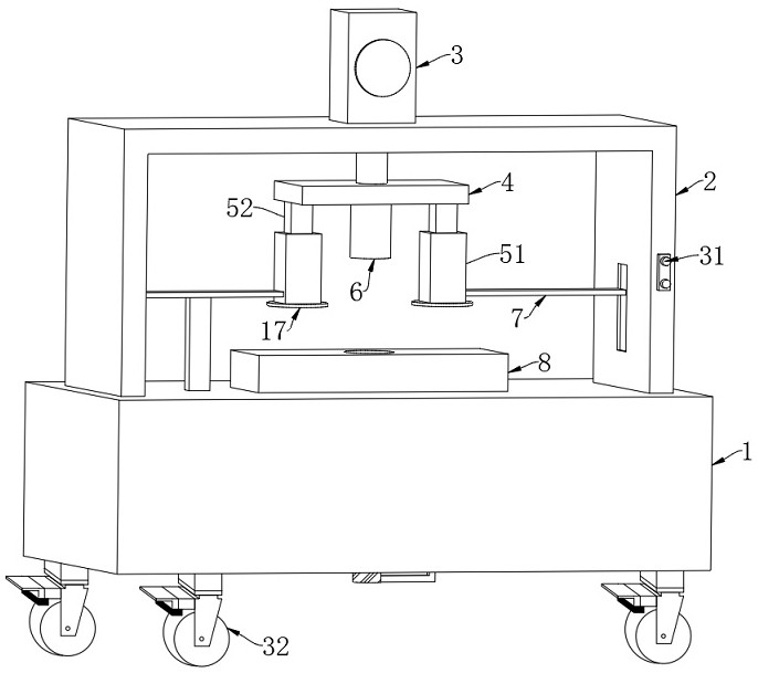
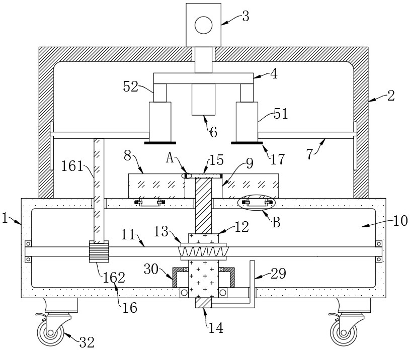
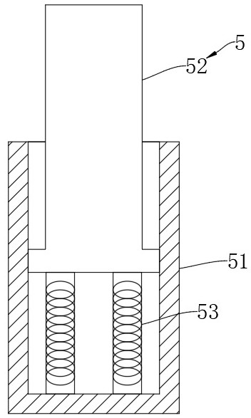
[0030] Such as Figure 1-5 As shown, a stainless steel plate punching equipment includes a workbench 1, a plurality of universal wheels 32 are fixedly connected to the lower end of the workbench 1, and the universal wheels 32 can be self-locking, and the setting of the universal wheels 32 is convenient for the staff to move In the whole device, a bracket 2 is fixedly connected to the workbench 1, and a cylinder 3 is arranged on the bracket 2, and a pressure plate 4 is fixedly connected to the output end of the cylinder 3, and two buffer mechanisms 5 and a punching head 6 are fixedly connected to the pressure plate 4, The buffer mechanism 5 includes a hollow seat 51, a support seat 52 and a buffer spring 53. The support seat 52 is fixedly connected to the pressing plate 4, and the hollow seat 51 is slidably connected to the support seat 52. Between the ho...


PUM


Abstract

The invention belongs to the field of stamping, and particularly relates to stainless steel plate stamping equipment which comprises a workbench, a support is fixedly connected to the workbench, an air cylinder is arranged on the support, the output end of the air cylinder is fixedly connected with a pressing plate, and two buffering mechanisms and a stamping head are fixedly connected to the pressing plate. Sliding rods are fixedly connected to the two buffering mechanisms correspondingly, and the sliding rods are slidably connected with the support. Through cooperation of a toothed bar and a gear, a worm can be matched with up-and-down movement of a stamping head to achieve forward and reverse rotation, under cooperation of a worm gear, a threaded sleeve can be matched with movement of the stamping head to rotate, then a threaded rod can drive a push plate to be matched with automatic sliding in the stamping process, and after stamping is finished, the push plate can be matched with return of the stamping head, the waste materials are automatically pushed out of a receding hole, and tedious manual taking and labor loss are avoided.

Description

technical field [0001] The invention belongs to the stamping field, in particular to a stainless steel plate stamping equipment. Background technique [0002] Stamping is to rely on the press and the lower mold body to apply external force to the sheet, strip, pipe, and profile to cause plastic deformation or separation, so as to obtain a workpiece (stamping) of the required shape and size. Forming processing method, stamping and Forging belongs to plastic processing (or pressure processing), collectively called forging, and the blanks for stamping are mainly hot-rolled and cold-rolled steel plates and steel strips. [0003] At present, the stainless steel plate often needs to be punched by stamping equipment in the production process. During the punching process, the stainless steel plate is placed on the lower mold, and the stainless steel plate is punched through the stamping head and the relief hole on the lower mold. However, after each punching, the generated waste is...

Claims


Application Information

Patent Timeline
Patent Type & Authority Applications(China)
IPC IPC(8): B21D28/34B21D28/26B21D28/04B21D45/02B21D55/00
CPCB21D28/34B21D28/26B21D28/04B21D45/02B21D55/00
Inventor 郑晓芳
Owner 郑晓芳
Why Eureka
Try Eureka