Target detection method based on micro-aircraft

A technology for micro-aircraft and target detection, applied in aircraft, unmanned aerial vehicles, instruments, etc., can solve problems such as limitations, complex target detection algorithms, affecting the large-scale application of UAVs, etc. chemical effect

Active Publication Date: 2020-06-05
BEIJING UNIVERSITY OF CIVIL ENGINEERING AND ARCHITECTURE
7 Cites 0 Cited by

AI-Extracted Technical Summary

Problems solved by technology

The error of UAV attitude recognition limits the control of UAV to UAV to a certain extent, thus affecting the large-scale application of UAV
[0008] Moreover, the target detection algorithm of the e...

Method used

Accelerometer will filter out high-frequency signal, and gyroscope will filter out low-frequency signal, and complementary filter is exactly different according to sensor characteristic, by different filter (high-pass or low-pass, complementary), then adds up to obtain whole Signals in the frequency band, for example, the accelerometer measures the inclination, its dynamic response is slow, and the signal is not available at high frequencies, so the high frequency can be suppressed by low-pass; the gyro responds quickly, and the inclination can be measured after integration, but due to zero drift, etc., The signal is not good in the low frequency band. Low-frequency noise can be suppressed by high-pass filtering. Combining the two, the advantages of the gyroscope and the accelerometer are combined to obtain a signal that is better at both high and low frequencies. Complementary filtering needs to select the switching frequency point, that is, the frequency of high-pass and low-pass.
Thus, the present invention is by the mode shown in Fig. 2, by target detection model, the output of the extra convolutional layer of three layers of decreasing step by step is merged to replace the fully connected layer of MBDSCNN shown in Fig. 3, and then three layers The output of the additional convolutional layer that decrease...

Abstract

The invention provides a target detection method based on a micro-aircraft. According to the method, the size of the model is reduced by using depth separable convolution; the generalization of the model is improved by using a multi-branch structure, an extra convolution layer is further added to a front-end network MBDSCNN structure of the target detection model, and the size of the extra convolution layer is set to be decreased layer by layer, so that the model can be predicted under a multi-scale condition. The established target detection model can combine the output of each extra convolution layer to replace the full connection layer of the MBDSCNN, and a non-maximum suppression layer (NMS) is added behind the full connection layer to output a detection result. Therefore, compared with the prior art, the method has the advantages that targets under various scales can be accurately recognized, and the detection result can be accurately output.

Application Domain

Aircraft componentsCharacter and pattern recognition +2

Technology Topic

Flight vehicleConvolution +5

Image

  • Target detection method based on micro-aircraft
  • Target detection method based on micro-aircraft
  • Target detection method based on micro-aircraft

Examples

  • Experimental program(1)

Example Embodiment

[0042] To make the objectives and technical solutions of the embodiments of the present invention clearer, the technical solutions of the embodiments of the present invention will be described clearly and completely in conjunction with the accompanying drawings of the embodiments of the present invention. Obviously, the described embodiments are part of the embodiments of the present invention, rather than all of the embodiments. Based on the described embodiments of the present invention, all other embodiments obtained by a person of ordinary skill in the art without creative work shall fall within the protection scope of the present invention.
[0043] Those skilled in the art can understand that, unless otherwise defined, all terms (including technical terms and scientific terms) used herein have the same meaning as those commonly understood by those of ordinary skill in the art to which the present invention belongs. It should also be understood that terms such as those defined in general dictionaries should be understood as having meanings consistent with the meanings in the context of the prior art, and unless defined as here, they will not be used in ideal or overly formal meanings. Explanation.
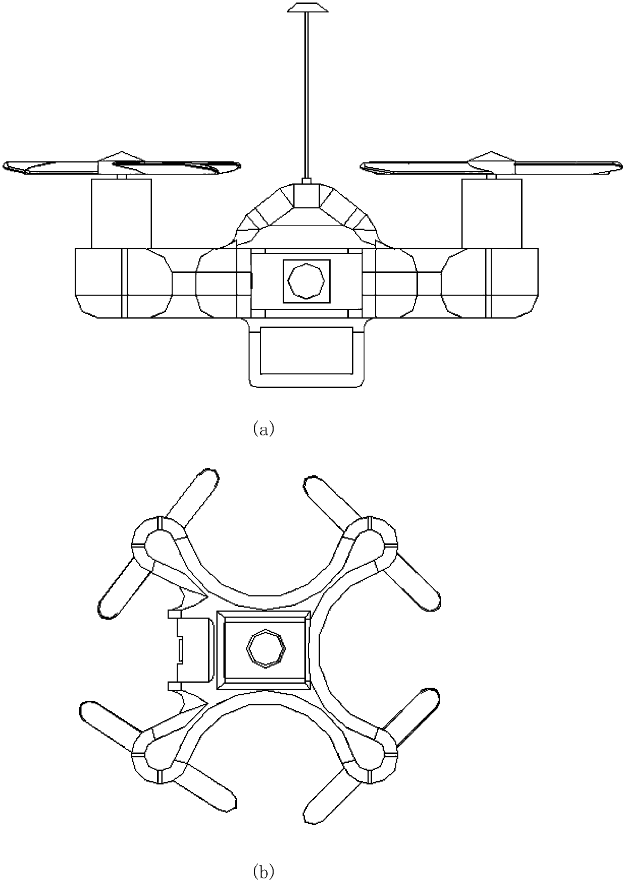
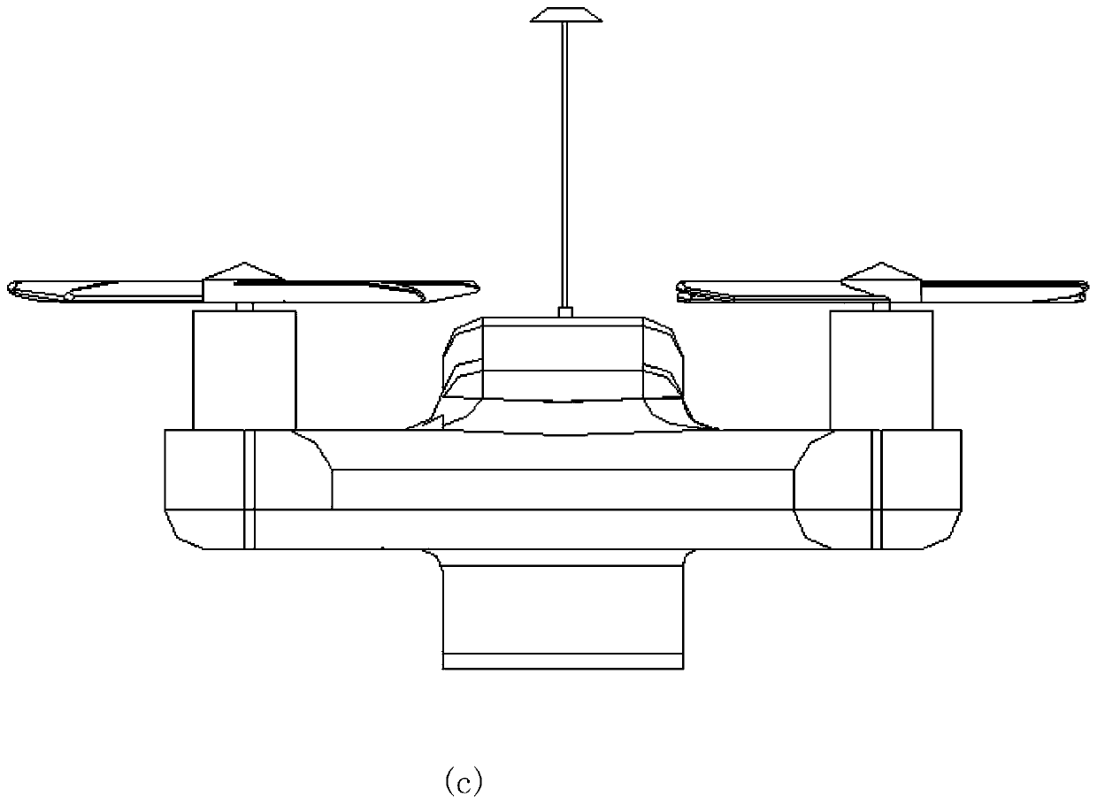
[0044] In one implementation, the target detection system provided by the present invention is set in figure 1 On the micro aircraft shown. The micro-aircraft includes: a four-axis flight platform, which includes a platform main body 1, four connecting shafts 2 extending outward are symmetrically provided at the four corners of the platform main body 1, and the distal ends of the four connecting shafts 2 are respectively provided with Four coreless motors. The motors of the four coreless motors extend axially and are respectively connected to a set of propellers 3. The coreless motors drive each set of propellers 3 to rotate and drive the micro aircraft to take off, land, fly or adjust the air attitude.
[0045] The shell of the four-axis flight platform adopts the overall design of Creo, and the shell adopts a streamlined design, which can greatly reduce air resistance. The whole adopts a symmetrical design, which can improve the stability when hovering. The feasibility of the design is verified by reserving various equipment interfaces and performing simulation assembly and simulation through the computer.
[0046] Therefore, the present invention can use target detection technology to detect specific targets in scenes that are not easy for personnel to enter, and help personnel to remotely detect the situation. For example, it can detect intelligence in the military, and it can also help rescuers quickly understand the disaster area in unclear disaster areas. Happening. Functionally, the micro four-axis target detection system can realize remote control, perform real-time target detection on the video stream collected by the camera, and return the video and detection results to the ground station.
[0047] Table 1 shows the corresponding performance indicators.
[0048] Table 1 Performance indicators of target detection system based on micro four-axis
[0049] name Design choices Remarks Control mode Remote control The wireless remote control distance is not more than 500m Maximum load 200g 200g Energy options lithium battery 7.4v Aircraft size 10x93mm motor Coreless motor 45000rpm
[0050] The micro aircraft also includes a flight control system and a wireless image transmission system. The flight control system uses STM32F103 as the main control chip and MPU6050 as the inertial navigation module. It uses complementary filtering on the collected gyroscope and accelerometer data to obtain stable output, and obtains the real-time attitude of the aircraft through the quaternion algorithm. Use cascade PID to maintain flight stability.
[0051] The wireless image transmission system of the micro-aircraft uses RTC6705 to realize analog image transmission in the 5.8GHz frequency band. The transmission power can be switched by pressing the button. The power range includes 25MW, 100MW, and 200MW, and the effective image transmission distance can reach 500M.
[0052] In a more preferred implementation mode, the above-mentioned micro-aircraft can specifically use SI2302MOS tube to drive 720 coreless motors as the power source of the aircraft; use MPU6050 chip as the inertial measurement unit (IMU), MPU6050 chip integrates gyroscope and accelerometer, through attitude The calculation algorithm can accurately obtain the three-axis attitude angle of the aircraft (ROLL, PITCH, YAW); realize remote control through the NRF24L01 wireless module, enhance the effective distance and effect of the remote control, and use the SMA antenna to amplify the wireless signal. Use the HC-05 Bluetooth module to transmit attitude data and camera object detection results.
[0053] In some implementations, the aircraft can use the 1S battery as the power supply. Since the voltage of the 1s battery is 4.2V when the battery is full, the battery voltage will change significantly during the operation of the aircraft, so the boost-buck circuit is used to ensure the main control Working voltage of chip, wireless module, Bluetooth module, etc. First use the ME2108A boost DC-DC chip to boost the input power and output a 5V voltage, and then input the 5V voltage to the MIC5219 voltage regulator chip to output a 3.3V voltage.
[0054] In order to cooperate with the NRF24L01 wireless module to realize remote control, the remote control of the micro aircraft is the same as the micro aircraft. It uses STM32F103 as the main control chip, uses 1s battery power, and uses XC6209 voltage regulator chip to provide a stable 3.3V working voltage for the main control chip. Use NRF24L01 wireless module to remotely control the micro aircraft. The remote control uses two joystick potentiometers to control the aircraft, and uses ADC to collect the voltage of the two potentiometers to obtain the desired value of the remote control. Use the OLED screen to display the real-time attitude angle data of the aircraft and the current expected value of the joystick. The main control chip of the remote control board collects the manipulated variables of the joystick through multi-channel AD. And send the desired value of the joystick to the micro four-axis through NRF24L01. The OLED screen on the remote controller can display the Euler angle of the aircraft and the expected value of the joystick through the wireless module. In order to achieve the above-mentioned functions. The Nrf24l01 wireless module needs to realize the function of full-duplex communication, but the Nrf24l01 itself does not have the function of full-duplex communication. Two NRF modules, one sends and the other receives. If you want two-way communication, you must switch the transceiver of the two modules. However, since the switching of modules takes time and the switching of two modules must be kept at the same time, it is very difficult to write the driver. So here we use the advanced function of NRF24L01+—Ack with payload, and use the response packet to carry user data, which can realize the switch-free sending and receiving state, and realize two-way communication. On the other hand, in order to ensure the safety of the micro-aircraft, the flight control program detects whether there is a signal in the 4 joystick channels every 3ms. If the remote control signal is not detected for more than 6ms, the micro-aircraft executes an automatic landing procedure.
[0055] In this process, in order to ensure the stable operation of the micro-aircraft, it is also necessary to calculate the attitude of the aircraft at the same time to control the operation of the aircraft correctly. In one implementation, the attitude calculation can fuse the three-axis acceleration and angular velocity data collected by the accelerometer and gyroscope on the MPU6050, and process the above data to obtain the real-time attitude angle of the miniature four-axis. The prerequisite for the micro four-axis to be able to fly stably is to be able to obtain the correct attitude angle data.
[0056] For the MPU6050, the accelerometer is more sensitive to the acceleration of the four-axis or the car, and the instantaneous value is used to calculate the inclination error; the angle obtained by the gyroscope is not affected by the acceleration, but the integral drift and temperature drift with the increase of time The error caused is relatively large. So these two sensors can make up for each other's shortcomings. Complementary filtering is to use the angle obtained by the gyroscope as the optimum in a short time, and take the average of the angles sampled from the acceleration regularly to correct the angle obtained by the gyroscope. Complementarity means that the gyroscope is more accurate in a short time, and it is mainly used; the accelerometer is more accurate when used for a long time, at this time increase its proportion.
[0057] The accelerometer needs to filter out high frequency signals, and the gyroscope needs to filter out low frequency signals. The complementary filter is to pass through different filters (high pass or low pass, complementary) according to the characteristics of the sensor, and then add to get the signal of the entire frequency band For example, when the accelerometer measures the inclination angle, its dynamic response is slow, and the signal is not available at high frequencies, so the high frequency can be suppressed by low pass; the gyro responds fast, and the inclination angle can be measured after integration, but due to zero drift, etc., in the low frequency range Signal is not good. Low-frequency noise can be suppressed by high-pass filtering. Combining the two will combine the advantages of the gyroscope and accelerometer to obtain a signal that is better at both high and low frequencies. Complementary filtering needs to select the switching frequency point, that is, the high-pass and low-pass frequencies.
[0058] Complementary filtering uses the angle obtained by the gyroscope as the optimal value in a short period of time, and takes the average of the acceleration values ​​sampled from the acceleration regularly to correct the angle obtained by the gyroscope to obtain a more accurate calculation of the micro air vehicle. attitude. It is more accurate to use a gyroscope in a short time, and it is mainly used; to use an accelerometer for a long time is more accurate, at this time increase its proportion to achieve complementarity. In the application of the present invention, the accelerometer is operated to filter out high-frequency signals, and the gyroscope is operated to filter out low-frequency signals. According to different sensor characteristics through complementary filters, through different filters (high pass or low pass), add Get the signal of the entire frequency band. In the present invention, different sensor signals are weighted and summed according to different weights in a complementary manner, and a complementary filtering method is used to realize micro four-axis attitude calculation. The specific calculation method is as follows:
[0059] Complementary filtering formula: gyro integral angle + = angular velocity *dt;
[0060] Angle deviation = acceleration angle-gyro integral angle;
[0061] Fusion angle = gyro angle + attenuation coefficient * angle deviation;
[0062] Angle deviation integral + = angle deviation;
[0063] Angular velocity = angular velocity + attenuation coefficient * angle deviation integral;
[0064] Refer to the specific steps of the posture calculation program flowchart Figure 4 Shown.
[0065] On this basis, considering the limited load capacity of the micro air vehicle, the target detection system carried by the micro air vehicle can be set on the Raspberry pi 4, connected to the camera set on the platform body 1 to collect video data, and implemented by deep learning technology Target detection of video streams. In view of the large model size and slow prediction speed of most deep learning models, the present invention can use multi-branch deep separable convolutional neural network and SingleShot MultiBoxDetector (MBDSCNN-SSD) to establish a target detection model, and use deep separable convolution to reduce The size of the model uses a multi-branch structure to improve the generalization of the model. Preferably, when a Coral USB accelerator is installed on the Raspberry pi 4, the MBDSCNN-SSD provided by the present invention can detect objects at a speed of 35fps.
[0066] The specific implementation is as follows:
[0067] The visual recognition unit provided by the present invention can be configured to include a Raspberry pi 4 miniature control unit and a Coral USB accelerator attached to the Raspberry pi 4 miniature control unit for receiving video data collected by the camera, And perform object detection on frames in the video data; wherein,
[0068] The Raspberry pi 4 miniature control unit is provided with a target detection model, and the target detection model includes a multi-branch depth separable convolutional neural network and a Single Shot MultiBox Detector operation module;
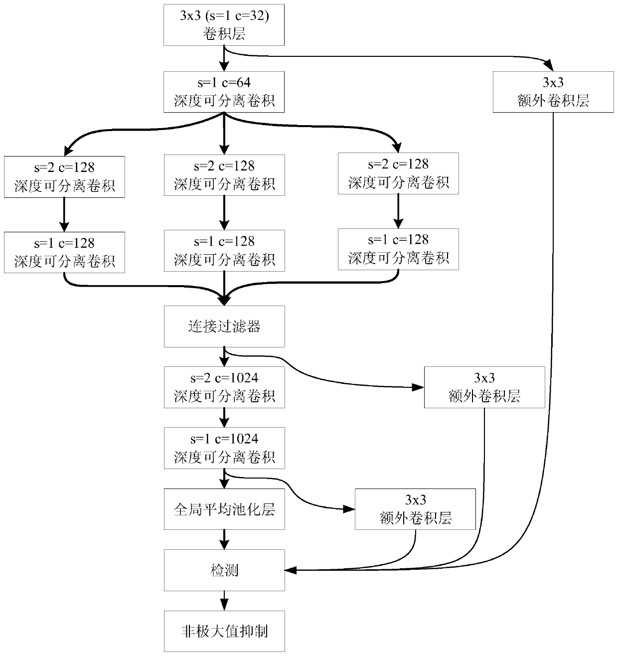
[0069] The multi-branch depth separable convolutional neural network is used to first perform 3x3 convolution on the frame images in the video data collected by the camera, and then perform deep separable convolution on the convolution result output by the 3x3 convolution, and then The data obtained by the depth separable convolution is input to the connection filter, and then the data output after the connection filter is sequentially subjected to two depth separable convolutions with different parameters and then output to the global average pooling layer;
[0070] The Single Shot MultiBox Detector arithmetic module is connected to MBDSCNN as a front-end network, which is used to output the convolution result of 3x3 convolution, the data output after connecting the filter, and the output after two depth separable convolution The data to the global average pooling layer are respectively subjected to 3x3 convolution, and then the three 3x3 convolution results and the pooled data obtained by the global average pooling layer are added to the non-maximum suppression layer for detection, and the detection results are output according to The detection result identifies the target in the video data collected by the camera.
[0071] In a more preferred implementation, the Single Shot MultiBox Detector operation module corresponds to the convolution result output by the 3x3 convolution in the pre-network MBDSCNN, corresponds to the data output after connecting the filter, and corresponds to the two depths. The data output to the global average pooling layer after separable convolution is provided with three additional convolutional layers of 3x3.
[0072] In each convolutional layer, s represents the convolution step size, and c represents the number of filters. The size of the three additional 3x3 convolutional layers decreases layer by layer. The specific parameters of other convolutional layers can be found in figure 2 The setting shown is: the first layer of the convolution result calculated by the 3x3 convolution is larger than the second layer calculated on the data output after the filter is connected in the third step The size of the extra convolutional layer of 3x3, the second layer calculated on the data output after connecting the filter in the third step is larger than the depth of the fifth layer in the third step The size of the third layer 3x3 extra convolutional layer for calculating the data output to the global average pooling layer after separable convolution; set the convolution step size corresponding to the depth separable convolution of two layers with three branch structures The number of and filters are both greater than the convolution step size and the number of filters for 3x3 convolution of the frames in the video data collected by the camera.
[0073] The front-end network MBDSCNN can be specifically set to include 1 convolution kernel 3×3 ordinary convolution, 9 depth separable convolutions, 1 global average pooling layer and a fully connected layer; among them, the 9 A depth separable convolution includes three branch structures, and each branch structure includes two layers with the same convolution step size s and the same number of filters c.
[0074] Thus, the present invention adopts figure 2 In the method shown, the output of the three additional convolutional layers that decrease layer by layer is merged and replaced by the target detection model image 3 As shown in the fully connected layer of MBDSCNN, the output of the three additional convolutional layers, which are gradually decreasing, is added to the non-maximum suppression layer (NMS) for detection, and the detection results are output, thereby achieving the technical effect of improving the efficiency of target detection. The reason is:
[0075] The traditional CNN model extracts features in the image through convolutional layers. As the number of convolutional layers increases, the more high-order features that can be extracted, the more superior the network's capabilities. However, the increase in the number of layers also reduces the efficiency of the model, and the requirements for running hardware are also greatly increased.
[0076] When depthwise separable convolution (Depthwise Separable Convolution) replaces the traditional convolution operation, because the depthwise separable convolution includes two layers: (1) using a convolution kernel for each input channel is called depthwise convolution (Depthwise convolution, DW); (2) Using a 1×1 convolution to merge the output of the DW is called pointwise convolution (PW).
[0077] In the standard convolutional layer, assume that the input feature map size is N i *N i , The number of channels is M, the size of the convolution kernel is N f *N f , The number of convolution kernels is K. The calculation amount of the convolutional layer is:
[0078] N i *N i *M*K*N f *N f (1)
[0079] The standard convolution operation includes two steps: filtering features through the convolution kernel and merging features to generate new high-level features. Depth separable convolution separates the two steps of standard convolution, namely DW and PW.
[0080] And reference Figure 5 As shown, the calculation amount of depth separable convolution is:
[0081] N i *N i *M*N f *N f +K*M*N i *N i (2)
[0082] Therefore, compare the calculation amount of standard convolution and depth separable convolution:
[0083]
[0084] K is the number of channels usually greater than 1, N f It is the size of the convolution kernel. Commonly used sizes include 3*3, 5*5, and 7*7. Therefore, the value of (3) is less than 1, and the depth separable convolution requires less calculation than the standard convolution.
[0085] Therefore, the present invention is based on the MBDSCNN including 1 convolution kernel 3×3 ordinary convolution, 9 depth separable convolutions, 1 global average pooling layer and a fully connected layer, in order to improve the expression of the model Ability to avoid "gradient disappearance" as the number of layers deepens, a multi-branch structure is further set up on MBDS-CNN, and the multi-branch structure is used to improve the generalization of the model and improve the accuracy and efficiency of target detection.
[0086] The above are only the embodiments of the present invention, and the description is relatively specific and detailed, but it should not be understood as a limitation to the patent scope of the present invention. It should be pointed out that for those of ordinary skill in the art, without departing from the concept of the present invention, several modifications and improvements can be made, and these all fall within the protection scope of the present invention.

PUM

no PUM

Description & Claims & Application Information

We can also present the details of the Description, Claims and Application information to help users get a comprehensive understanding of the technical details of the patent, such as background art, summary of invention, brief description of drawings, description of embodiments, and other original content. On the other hand, users can also determine the specific scope of protection of the technology through the list of claims; as well as understand the changes in the life cycle of the technology with the presentation of the patent timeline. Login to view more.

Similar technology patents

Multi-channel aggregated confrontation sample generation method, system and terminal

ActiveCN114861893AStrong generalizationimprove generalization
Owner:SOUTHWEST PETROLEUM UNIV

Road network difference method and device, electronic equipment and storage medium

PendingCN114429434Aimprove accuracyimprove generalization
Owner:HANHAI INFORMATION TECH SHANGHAI

Extreme multi-label learning method based on space-time network clustering reduction integration

PendingCN114676252AEnhanced Representational Capabilitiesimprove generalization
Owner:YUNNAN UNIV

Classification and recommendation of technical efficacy words

  • real-time detection
  • improve generalization

Failure detecting equipment of power communication transmission channel, failure detecting system and method

ActiveCN101825667Areal-time detection
Owner:NORTH CHINA ELECTRICAL POWER RES INST +2

A fatigue detection method based on deep learning face posture estimation

InactiveCN109919049Aingenious designreal-time detection
Owner:以萨技术股份有限公司 +1

Method and terminal for detecting wearing of earphone

InactiveCN106982403Aimprove accuracyreal-time detection
Owner:SHENZHEN GIONEE COMM EQUIP

High frequency injection-based oxygen sensor internal resistor detection circuit

PendingCN106932644AImprove output voltagereal-time detection
Owner:凯晟动力技术(嘉兴)有限公司

Multi-task reinforcement learning method for realizing parallel task scheduling

InactiveCN110580196Aimprove generalization
Owner:BEIJING UNIV OF POSTS & TELECOMM

Ozonosphere forecasting algorithm based on artificial intelligence

ActiveCN113901714Aavoid mathematical modelingimprove generalization
Owner:NAT UNIV OF DEFENSE TECH

Multi-channel aggregated confrontation sample generation method, system and terminal

ActiveCN114861893AStrong generalizationimprove generalization
Owner:SOUTHWEST PETROLEUM UNIV

Road network difference method and device, electronic equipment and storage medium

PendingCN114429434Aimprove accuracyimprove generalization
Owner:HANHAI INFORMATION TECH SHANGHAI
Why Eureka
Try Eureka