Clinker drying device for cement processing

A drying device and clinker technology, which is applied in the field of cement processing, can solve the problems of affecting the drying effect and uneven heating of clinker, so as to improve the drying effect, avoid excessive pressure, and ensure the drying effect

Inactive Publication Date: 2020-06-05
黄学永
View PDF0 Cites 1 Cited by
  • Summary
  • Abstract
  • Description
  • Claims
  • Application Information

AI Technical Summary

Problems solved by technology

[0003] At present, during the working process of the drying device for clinker, most of the clinker is placed in it, which easily leads to uneven heating of some clinker, thus affecting the drying effect

Method used


Image

  • Clinker drying device for cement processing
  • Clinker drying device for cement processing
  • Clinker drying device for cement processing

Examples


Embodiment 1

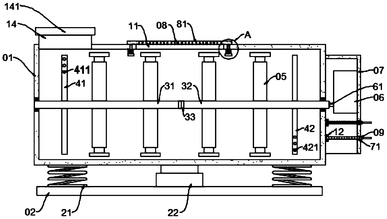
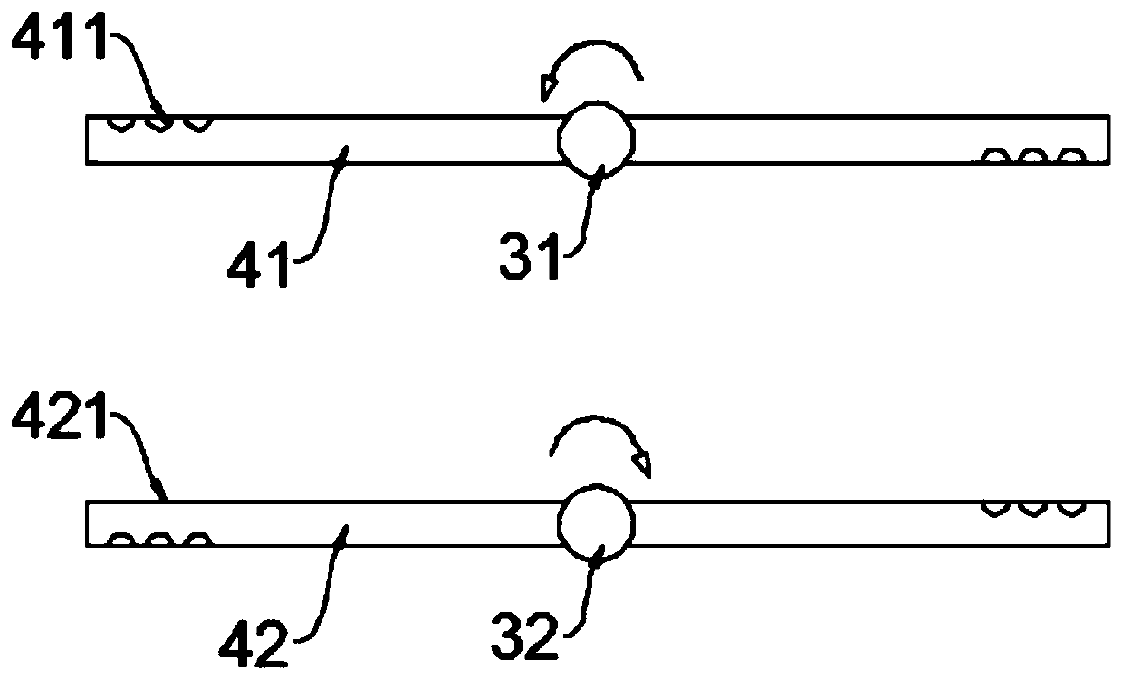
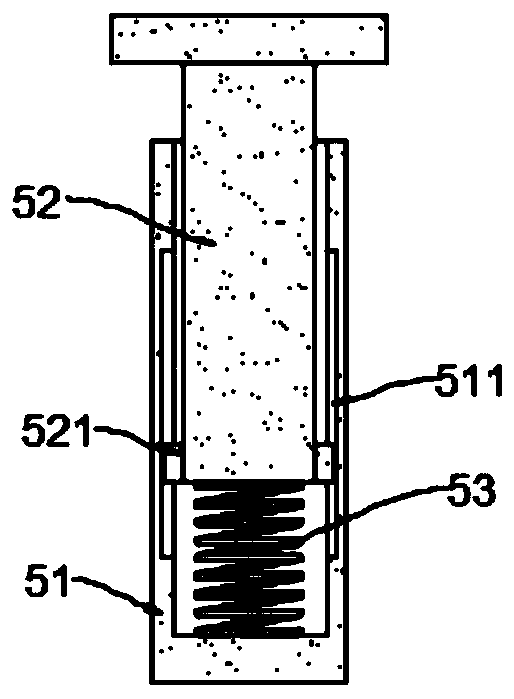
[0026] see Figure 1~3 , in an embodiment of the present invention, a clinker drying device for cement processing includes a box body 01, a base 02 and a hot air blower 06, and a feed pipe 14 is connected to the top shell wall of the box body 01, and the feed pipe 14 A feed pipe valve 141 is installed on the top; a horizontal hollow shaft is arranged in the box body 01, and the hollow shaft is rotatably connected in the box body 01, and a material turning member 05 and a plurality of sets of feeding parts perpendicular to the hollow shaft are fixed on the hollow shaft. Air pipes, the number of the air pipes in each group is two and air holes are provided on the air pipes; the output end of the hot air blower 06 is connected with an air supply pipe 61, and the air supply pipe 61 is connected with the hollow rotating shaft through a rotating joint. During work, The hot air generated by the hot air blower 06 is ejected through the air holes, and the hollow rotating shaft will rot...

Embodiment 2

[0036] see figure 1 , 4 ~5, the embodiment of the present invention expands the function on the basis of embodiment 1, specifically:

[0037] The top shell wall of the box body 01 is provided with an exhaust hole 11, and the exhaust hole 11 is provided with a baffle plate 08, and the baffle plate 08 is evenly distributed with micropores 81. During operation, the excess heat in the box body 01 passes through The discharge speed of the micropores 81 is relatively slow, so that the pressure in the box 01 is increased, and the drying efficiency is improved.

[0038]In order to ensure the safety of the work, in this embodiment, the bottom of the baffle plate 08 is fixed with a vertically arranged guide rod 82, and the guide rod 82 slides through the perforation 13 opened in the top shell wall of the box body 01. The guide rod 82 The limit block 821 is fixed at the bottom of the bottom, and a resistance spring 822 is connected between the limit block 821 and the inner wall of the ...


PUM


Abstract

The invention relates to a clinker drying device for cement processing, which comprises a box body, a base and an air heater, a feeding pipe is connected to the shell wall of the top of the box body,and a feeding pipe valve is installed on the feeding pipe; wherein a transverse hollow rotating shaft is arranged in the box body, the hollow rotating shaft is rotatably connected in the box body, a material turning piece and a plurality of groups of gas conveying pipes perpendicular to the hollow rotating shaft are fixed on the hollow rotating shaft, the number of each group of gas conveying pipes is two, and gas holes are formed in the gas conveying pipes; and the output end of the air heater is connected with an air supply pipe, and the air supply pipe is connected with the hollow rotatingshaft through a rotating joint. The hollow rotating shaft is arranged in the box body, the hollow rotating shaft is connected with the air conveying pipe and a material overturning piece, and the hollow rotating shaft can drive the material overturning piece to rotate through supply of hot air flow, so that clinker in the box body is overturned, and the drying effect is guaranteed.

Description

technical field [0001] The invention relates to the field of cement processing, in particular to a clinker drying device for cement processing. Background technique [0002] The industrialized cement production process is as follows: firstly, limestone, water, iron ore and other raw materials are crushed, and then preliminary mixing is carried out, and then other raw materials are added in proportion, after crushing, secondary mixing is carried out, and then Preheat all the raw materials to decompose them, discard the useless components, then burn the clinker, and finally dry and grind them into powder. [0003] At present, during the working process of the drying device for clinker, most of the clinker is placed in it, which easily leads to uneven heating of part of the clinker, thereby affecting the drying effect. Contents of the invention [0004] The object of the present invention is to provide a clinker drying device for cement processing to solve the above problems...

Claims


Application Information

Patent Timeline
Patent Type & Authority Applications(China)
IPC IPC(8): C04B7/47
CPCC04B7/47
Inventor 黄学永
Owner 黄学永
Why Eureka
Try Eureka