Floorslab thickness control tool

A technology of thickness control and tools, which is applied in the direction of construction, building structure, and building material processing, and can solve the problems of concrete being difficult to vibrate and compact, displacement, and floor damage

Pending Publication Date: 2020-06-05
中建四局建设发展有限公司 +1
View PDF0 Cites 3 Cited by
  • Summary
  • Abstract
  • Description
  • Claims
  • Application Information

AI Technical Summary

Problems solved by technology

1) During the pouring process of the floor, within the range of the floor thickness controller, that is, the concrete around the outer wall of the PVC pipe is not easy to vibrate and compact. There are two reasons for this, one is the connection between the PVC pipe and the clamping parts Most of them are realized by clamping. Whether the clamping part and the PVC pipe vibrate, or the clamping part and the PVC pipe vibrate at the same time, it is very easy to cause displacement between the PVC pipe and the clamping part; the second is In order to ensure the stability of the installation, the connection between the clamping parts and the formwork for floor pouring is mostly rigid connection, lack of cushioning design, excessive vibration will easily lead to connection gaps at the joint between the clamping parts and the formwork, resulting in reduced positioning of the PVC pipe. Even positioning failure occurs, so the concrete vibrating equipment cannot be too close to the PVC pipe for vibrating operations, which in turn causes the concrete around the outer wall of the PVC pipe to be difficult to vibrate and compact
2) After the concrete is solidified, the PVC pipe forms a reserved hole in the floor in the state of an inlaid device, which needs to be repaired later, but the PVC pipe needs to be removed before repairing the hole, which is not only difficult to remove problems, and it is easy to cause damage to the floor, and most of the removed PVC pipes become waste products, resulting in waste of resources
3) The plugging operation of the reserved hole caused by the thickness control of the floor is very difficult

Method used


Image

  • Floorslab thickness control tool
  • Floorslab thickness control tool

Examples


Embodiment Construction

[0020] In order to facilitate the understanding of those skilled in the art, the structure of the present invention will be further described in detail with the embodiments in conjunction with the accompanying drawings:

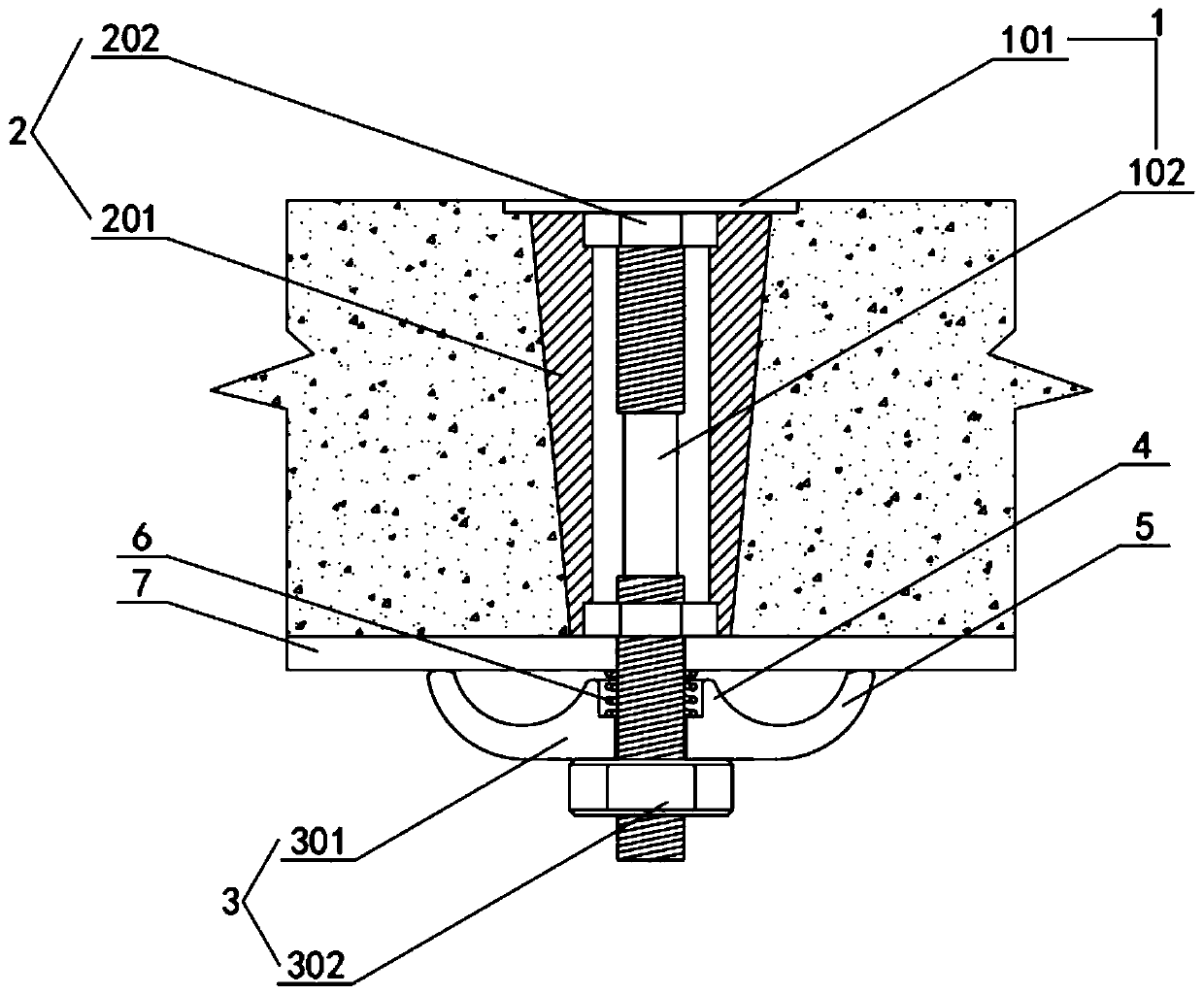
[0021] refer to Figure 1-2 , a floor thickness control tool, including a pre-embedded mechanism 1, a multifunctional casing mechanism 2 and a locking mechanism 3, the pre-embedded mechanism 1 includes a fixed steel plate 101 and a fixed screw 102 fixed to the bottom of the fixed steel plate 101 , the upper and lower ends of the fixed screw 102 are respectively provided with corresponding locking external threads, and the diameter of the middle part of the fixed screw 102 is smaller than the minor diameter of the locking external threads; Fixing piece 201, the center of the rounded table-shaped fixing piece 201 is vertically provided with a corresponding communication hole, and the upper and lower ends of the communication hole are respectively inlaid with co...


PUM


Abstract

The invention relates to a floorslab thickness control tool comprising a pre-burying mechanism, a multifunctional casing mechanism and a locking mechanism. The pre-burying mechanism comprises a fixingsteel plate and a fixing screw rod fixedly connected with the bottom of the fixing steel plate; the upper and lower ends of the fixing screw rod are each provided with corresponding locking externalthreads; the multifunctional casing mechanism comprises a fixing part shaped like an inverted circular truncated cone, and the fixing part shaped like the inverted circular truncated cone is coordinated with the locking external threads on the fixing screw rod through locking nuts installed at the upper and lower ends of the fixing part to be locked on fixing screw rod in a sleeving mode; the locking mechanism comprises a locking fixing part arranged at the bottom of the fixing screw rod in a sleeving manner; and a locking nut is locked and installed at the position, below the locking fixing part, of the fixing screw rod. According to the floorslab thickness control tool, it can be ensured that the vibrating compaction of concrete within the range of the floorslab thickness control tool isachieved effectively, and the convenient removal of the floorslab thickness control tool can be achieved.

Description

technical field [0001] The invention relates to a floor slab thickness control tool, which is mainly used for pouring thickness control of slab concrete. Background technique [0002] The slab is a horizontally stressed component of the structure and one of the main components of structural safety. The pouring thickness of the slab concrete is an important architectural index in construction. If the control of the slab thickness is not strict, it will cause serious quality problems. Traditionally, the thickness control of floor slabs is controlled by inserting drill method. The inserting drill method is not only troublesome in construction, but also easily leads to uneven control of floor thickness due to the randomness of operators and different technical levels. In order to ensure that the thickness of the floor slab can be effectively controlled and uniform, most of the floor thickness controllers are directly used to control the pouring thickness of the floor slab. At p...

Claims


Application Information

Patent Timeline
Patent Type & Authority Applications(China)
IPC IPC(8): E04G21/10
CPCE04G21/10
Inventor 何强龙俞利春彭振峰陈业伟路锋
Owner 中建四局建设发展有限公司
Why Eureka
Try Eureka