Gearbox transmission structure

A gearbox transmission and transmission structure technology, which is applied in the field of gearboxes to achieve the effects of low failure rate, convenient installation and good reliability

Pending Publication Date: 2020-06-05
CHONGQING SHINERAY AGRI MACHINERY
View PDF1 Cites 0 Cited by
  • Summary
  • Abstract
  • Description
  • Claims
  • Application Information

AI Technical Summary

Problems solved by technology

However, there is no report about this gearbox transmission structure.

Method used


Image

  • Gearbox transmission structure

Examples


Embodiment Construction

[0026] The specific embodiments provided by the present invention will be described in detail below in conjunction with the accompanying drawings.

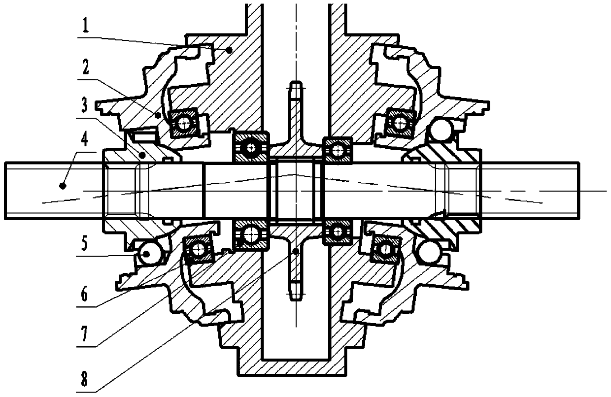
[0027] The reference signs and components involved in the accompanying drawings are as follows:

[0028] 1. Cabinet 2. V-type output side cover

[0029] 3. Transmission conversion sleeve 4. Horizontal output shaft

[0030] 5. Torque transmission steel ball 6. V-type output side cover bearing

[0031] 7. Horizontal output shaft bearing 8. Driven sprocket

[0032] Please refer to figure 1 , figure 1 It is a structural schematic diagram of a gearbox transmission structure of the present invention. A gearbox transmission structure, the gearbox transmission structure includes a box body 1; a horizontal output shaft bearing 7 is installed in the box body 1; a driven chain is sleeved on the horizontal output shaft bearing 7 wheel 8; the two ends of the driven sprocket 8 are equipped with horizontal output shaft bearing 7 bearings; ...


PUM


Abstract

The invention relates to a gearbox transmission structure. The gearbox transmission structure includes a box body; a horizontal output shaft is installed in the box body; a driven chain wheel sleevesthe horizontal output shaft; horizontal output shaft bearings are installed at the two ends of the driven chain wheel; transmission conversion sleeves are arranged on the outer sides of the horizontaloutput bearings, and the transmission conversion sleeves sleeve the horizontal output shaft; V-shaped output side covers are installed on the outer circumferences of the transmission conversion sleeves; and when the driven chain wheel rotates, the horizontal output shaft is driven to rotate, and the horizontal output shaft and the V-shaped output side covers rotate synchronously. The gearbox transmission structure has the advantages of convenient installation, low failure rate and good reliability. The functional defects of a micro tiller and a management machine in the market are successfully overcome, the multifunctional and one machine multi-purpose characteristics are achieved, and the needs of users in different regions and environments can be met.

Description

technical field [0001] The invention relates to the technical field of gearboxes, in particular to a transmission structure of a gearbox. Background technique [0002] At present, there is only one output interface for micro tillage machines and management machines on the market, and most of them are horizontal axis output, and very few are V-shaped structure output. However, the transmission structure in the prior art gearbox has the following defects and deficiencies: [0003] First of all, at present, the cutting tools that use the horizontal axis output should avoid the box, which will inevitably lead to missing tillage. This will cause the whole machine to rely on the box to turn the row of missing tillage when the machine is working on hard ground and clay due to part of the missing tillage on the ground. The soil is broken, so that the resistance of the machine is very large and the load of the whole machine is increased. If it encounters hardness or wasteland land, ...

Claims


Application Information

Patent Timeline
Patent Type & Authority Applications(China)
IPC IPC(8): F16H57/021F16H57/023F16H57/031A01B33/08
CPCA01B33/082F16H57/021F16H57/023F16H57/031F16H2057/02056
Inventor 王艺霖王显钢陈刘阳刘滨
Owner CHONGQING SHINERAY AGRI MACHINERY
Why Eureka
Try Eureka