
Pipeline rotating joint

A technology of rotary joints and pipes, applied in the directions of pipes/pipe joints/pipe fittings, adjustable connections, passing elements, etc., can solve the problems of increasing the displacement space configuration requirement, improving the engineering difficulty factor, and the large amount of pipeline moving engineering, etc. Improve the stability of the structure configuration, the guarantee of structural strength, and the lightness of the overall structure

Pending Publication Date: 2020-06-05
高道密封科技(苏州)有限公司
View PDF0 Cites 2 Cited by
  • Summary
  • Abstract
  • Description
  • Claims
  • Application Information

AI Technical Summary

Problems solved by technology

However, when the receiving position changes, it is necessary to move the connected pipeline as a whole or perform additional pipeline extension operations, which increases the application cost
Moreover, the overall weight of the connected pipeline is relatively large, so the pipeline moving is a large amount of work for the staff, and the corresponding work intensity is also improved, which reduces the work efficiency and also increases the configuration requirements for the displacement space. The operability is low, which increases the difficulty factor of the project

Method used


Image

  • Pipeline rotating joint
  • Pipeline rotating joint
  • Pipeline rotating joint

Examples


Embodiment Construction

[0024] The present invention will be further described below in conjunction with the accompanying drawings and specific embodiments.

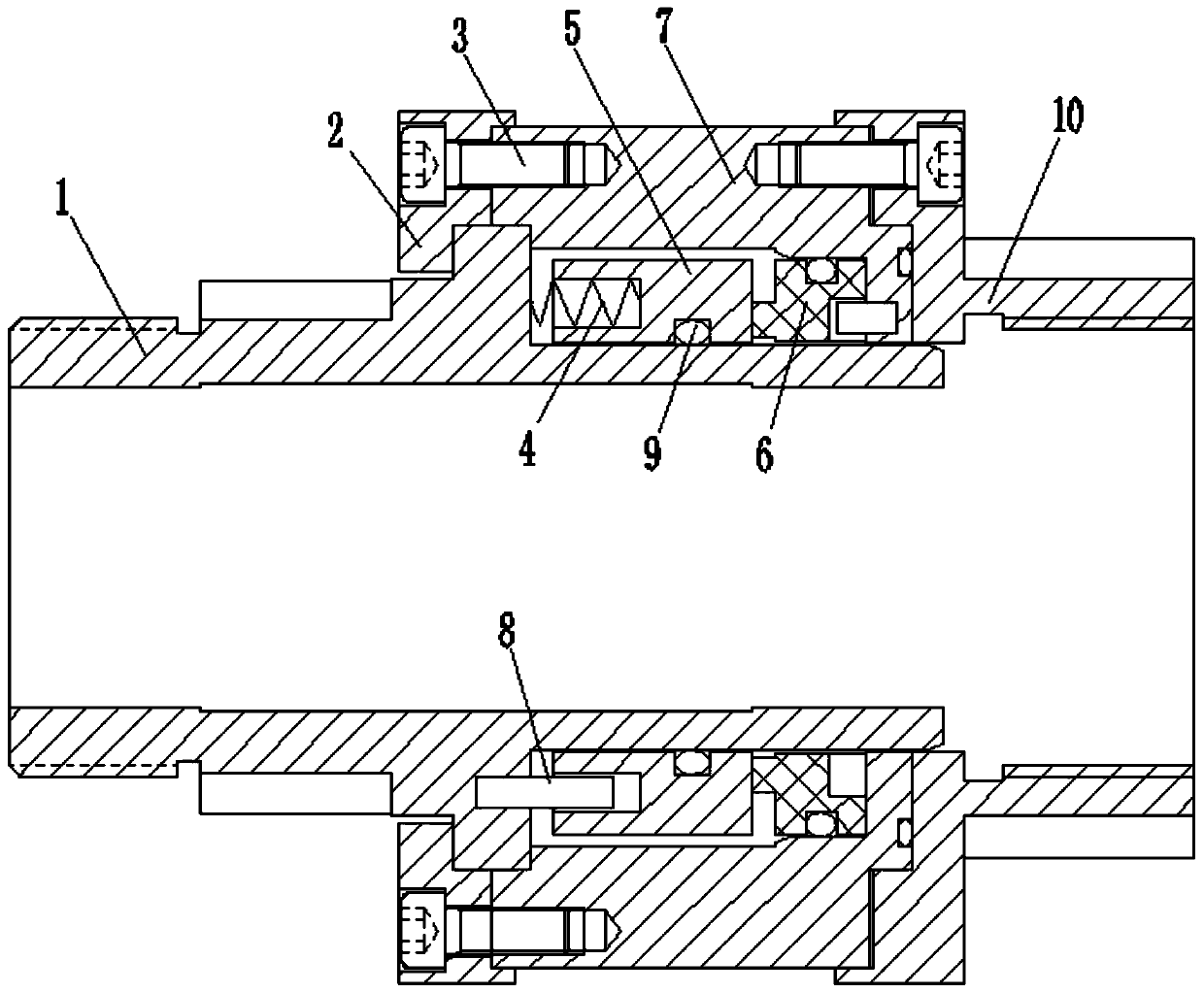
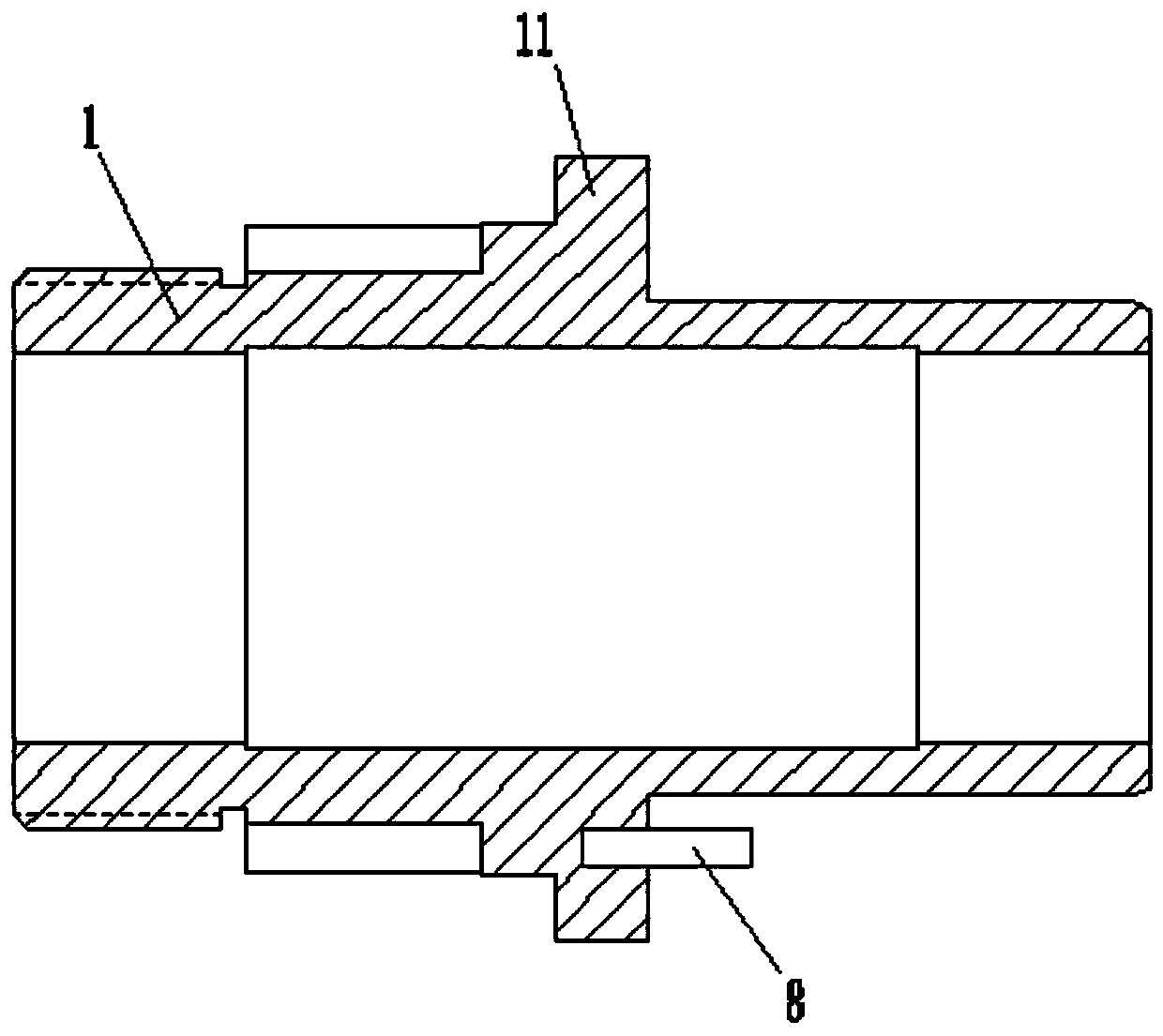
[0025] The structure of the rotary joint is as follows figure 1 As shown, it is composed of a shaft sleeve 1, a gland 2, a moving ring 5, a static ring 6, a static ring seat 7 and a pressure plate 10. The shaft sleeve 1 and the pressing plate 10 are sleeved and installed on the ends of the two pipes respectively. The structure of the shaft sleeve 1 integrally formed of nylon material is as follows: figure 2 As shown, the outer surface of the center is coaxially provided with an annular protrusion as the limiting convex ring 11, and the gland 2 and the static ring seat 7 sleeved on the shaft sleeve 1 are respectively arranged on both sides of the limiting convex ring 11. The structure of pressing plate 10 is as image 3 It is shown that the end facing the static ring seat 7 is sequentially arranged as a stepped ring structure with gradually ...


PUM


Abstract

The invention discloses a pipeline rotating joint applied to the field of pipeline transportation. The pipeline rotating joint structurally comprises a shaft sleeve, a pressing cover, a moving ring, astatic ring, a static ring seat and a pressing plate, wherein the pressing cover and the static ring seat are correspondingly arranged on two sides of a limiting convex ring of the shaft sleeve to realize bolt fixed connection, the other end part of the static ring seat is fixedly connected with a pressing plate bolt arranged at the end part of another pipeline in a sleeve mode, the bottom makescontact with the outer surface of the shaft sleeve, one end of the moving ring is in synchronous pin connection with the limiting convex ring, a limiting compression spring is arranged, the other endof the moving ring is tightly attached to the end face of the static ring, and the other end face of the static ring is in pin connection with the static ring seat. According to the pipeline rotatingjoint, flexible movement of the pipeline position is achieved while the channel sealing effect is guaranteed, conversion of the rear layout direction can be achieved directly through single-section rotation when a path or a port is converted, overall carrying operation of connecting pipeline components is avoided, and therefore the space configuration requirement is lowered, the application rangeof the pipeline structure is widened, and the operation flexibility and the operation cheapness are improved.

Description

technical field [0001] The invention relates to a pipeline rotary joint used in the pipeline transportation field. Background technique [0002] Pipeline transportation is a long-distance transportation method for liquid and gas materials using pipelines as a means of transportation. In the application process, one end of the transportation channel is used as the material inlet, and the other end is used as the material outlet and placed in the corresponding receiving position. In order to ensure the sealing effect of the connection of the transportation channel, the ports of the pipeline are usually fixedly connected to ensure the quality of transmission. However, when the receiving position is changed, it is necessary to move the connected pipeline as a whole or perform an additional pipeline extension operation, which increases the application cost. Moreover, the overall weight of the connected pipeline is relatively large, so the pipeline moving is a large amount of wo...

Claims


Application Information

Patent Timeline
Patent Type & Authority Applications(China)
IPC IPC(8): F16L27/08
CPCF16L27/0808
Inventor 施益丰黄虎陆勇
Owner 高道密封科技(苏州)有限公司
Learn More