Supercharge Your Innovation With Domain-Expert AI Agents!

Compound peripheral hole and tunnel efficient vibration reduction and smooth-surface smooth-bottom blasting method

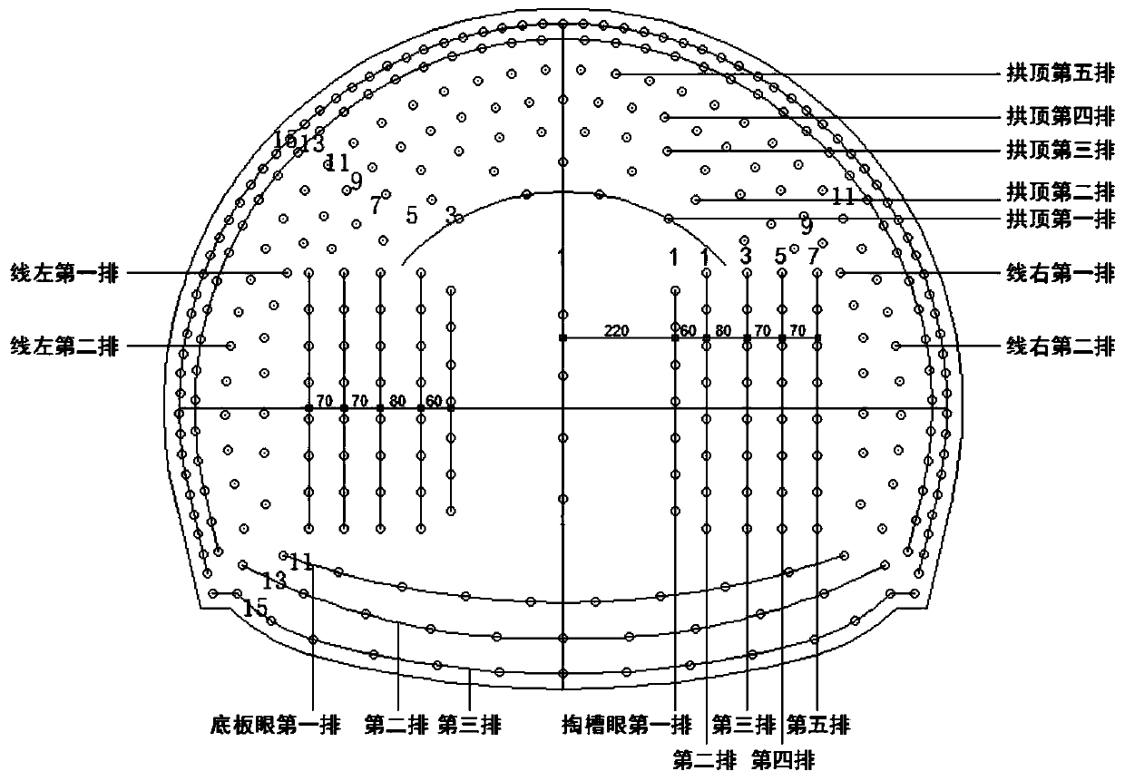
A peripheral eye and compound technology, which is applied in the fields of smooth surface and light bottom blasting, compound peripheral eye and high-efficiency vibration reduction in tunnels, can solve the problems of excessive local over-excavation, low utilization rate of blastholes, and many local blocks, so as to reduce construction Safety risks, increase the self-stabilization time of surrounding rock, and reduce the effect of loosening circle of surrounding rock

Active Publication Date: 2020-06-05
CHINA RAILWAY 18TH BUREAU GRP CO LTD
View PDF7 Cites 9 Cited by
  • Summary
  • Abstract
  • Description
  • Claims
  • Application Information

AI Technical Summary

Problems solved by technology

Existing tunnel blasting is mostly the full-face drilling and blasting method, which has the following disadvantages: (1) The effect of smooth blasting is not well controlled, and there is a lot of local overbreak, and in other places, there is a lot of undercut and secondary blasting is required; It is limited, between 3.8 and 4.2m, and it is difficult to break through 4.5m; (3) Although the cut hole is deep, the utilization rate of the blasthole is low, about 80%; (4) The blasting vibration is large, and the surrounding rock loose circle is large, There are many local blocks, and the security risk is high

Method used


Image

  • Compound peripheral hole and tunnel efficient vibration reduction and smooth-surface smooth-bottom blasting method
  • Compound peripheral hole and tunnel efficient vibration reduction and smooth-surface smooth-bottom blasting method
  • Compound peripheral hole and tunnel efficient vibration reduction and smooth-surface smooth-bottom blasting method

Examples


Embodiment Construction

[0028] The following will clearly and completely describe the technical solutions in the embodiments of the present invention with reference to the accompanying drawings in the embodiments of the present invention. Obviously, the described embodiments are only some, not all, embodiments of the present invention. Based on the embodiments of the present invention, all other embodiments obtained by persons of ordinary skill in the art without making creative efforts belong to the protection scope of the present invention.

[0029] The purpose of the present invention is to provide a compound peripheral eye and tunnel high-efficiency vibration reduction and smooth bottom blasting method to solve the problems in the above-mentioned prior art. The cycle footage is increased to 5.0m, while over- and under-excavation are controlled, blasting vibration is reduced, surrounding rock loose circle is reduced, surrounding rock self-stabilization time is increased, and construction safety ris...


PUM

PropertyMeasurementUnit
Lengthaaaaaaaaaa

Abstract

The invention discloses a compound peripheral hole. The compound peripheral hole comprises a plurality of peripheral deep holes and a plurality of peripheral short holes, the depth direction of the peripheral deep holes is inclined relative to the contour line of a tunnel, the peripheral short holes are formed in the contour line of the tunnel, and the peripheral deep holes are of a non-coupling spaced charging structure. The invention further discloses a tunnel efficient vibration reduction and smooth surface smooth-bottom blasting method. The method comprises the following steps that wedge-shaped compound slotting is adopted in slotting in the tunnel, and a plurality of middle cutholes, cutholes, inner ring holes, auxiliary holes, bottom plate holes and the compound peripheral holes areformed; the number of the middle cutholes, the number of the cutholes, the number of the inner ring holes, the number of the compound peripheral holes, the number of the auxiliary holes and the numberof the bottom plate holes are determined according to the tunnel size; and the middle cutholes, the cutholes, the inner ring holes and the bottom plate holes are all of a continuous charging structure. According to the tunnel efficient vibration reduction and smooth-surface smooth-bottom blasting method, on the premise that the drilling depth and the explosive loading amount are basically unchanged, the blasting circulation footage is increased to 5.0 meters, and meanwhile the construction safety risk is reduced.

Description

technical field [0001] The invention relates to the technical field of tunnel blasting, in particular to a compound peripheral eye and tunnel efficient vibration reduction, smooth surface and smooth bottom blasting method. Background technique [0002] With the rapid development of urban rail transit, there are more and more tunnel constructions. Existing tunnel blasting is mostly the full-face drilling and blasting method, which has the following disadvantages: (1) The effect of smooth blasting is not well controlled, and there is a lot of local overbreak, and in other places, there is a lot of undercut and secondary blasting is required; It is limited, between 3.8 and 4.2m, and it is difficult to break through 4.5m; (3) Although the cut hole is deep, the utilization rate of the blasthole is low, about 80%; (4) The blasting vibration is large, and the surrounding rock loose circle is large, There are many localized blocks, and the security risk is high. Contents of the i...

Claims


Application Information

Patent Timeline
IPC IPC(8): F42D1/08F42D3/04
CPCF42D1/08F42D3/04
Inventor 张馨刘飞香
Owner CHINA RAILWAY 18TH BUREAU GRP CO LTD
Features
  • R&D
  • Intellectual Property
  • Life Sciences
  • Materials
  • Tech Scout
  • Unparalleled Data Quality
  • Higher Quality Content
  • 60% Fewer Hallucinations
Learn More