
fuel high pressure pump

A high-pressure pump and fuel technology, applied in the direction of fuel injection pump, fuel injection device, liquid fuel engine, etc., to achieve the effect of simple structure design

Active Publication Date: 2019-07-23
ROBERT BOSCH GMBH
View PDF6 Cites 0 Cited by
  • Summary
  • Abstract
  • Description
  • Claims
  • Application Information

AI Technical Summary

Problems solved by technology

[0003] The problem on which the invention is based is solved by the fuel high-pressure pump according to the invention

Method used


Image

  • fuel high pressure pump
  • fuel high pressure pump
  • fuel high pressure pump

Examples


Embodiment Construction

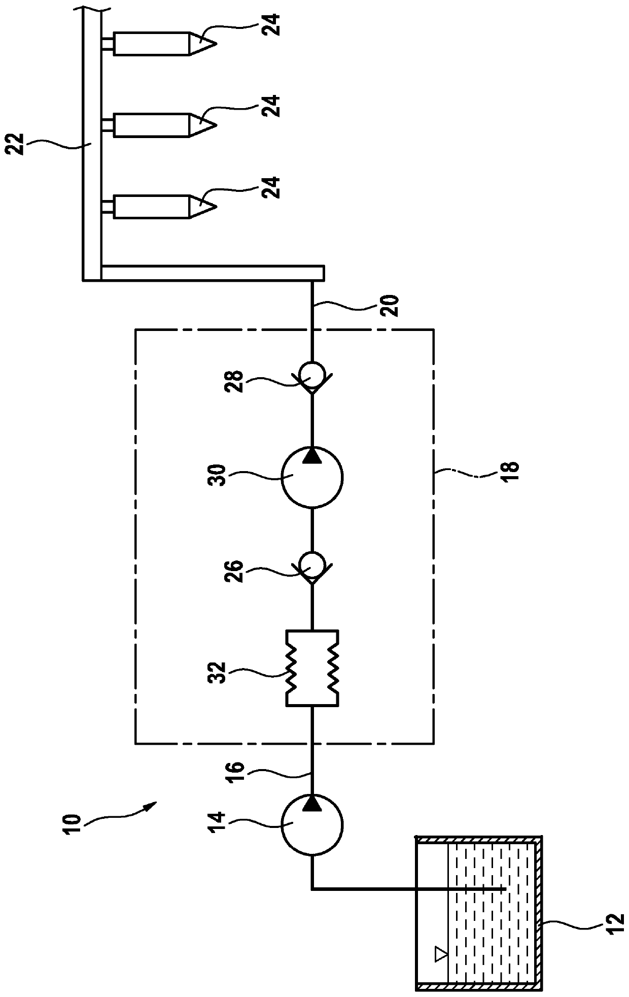
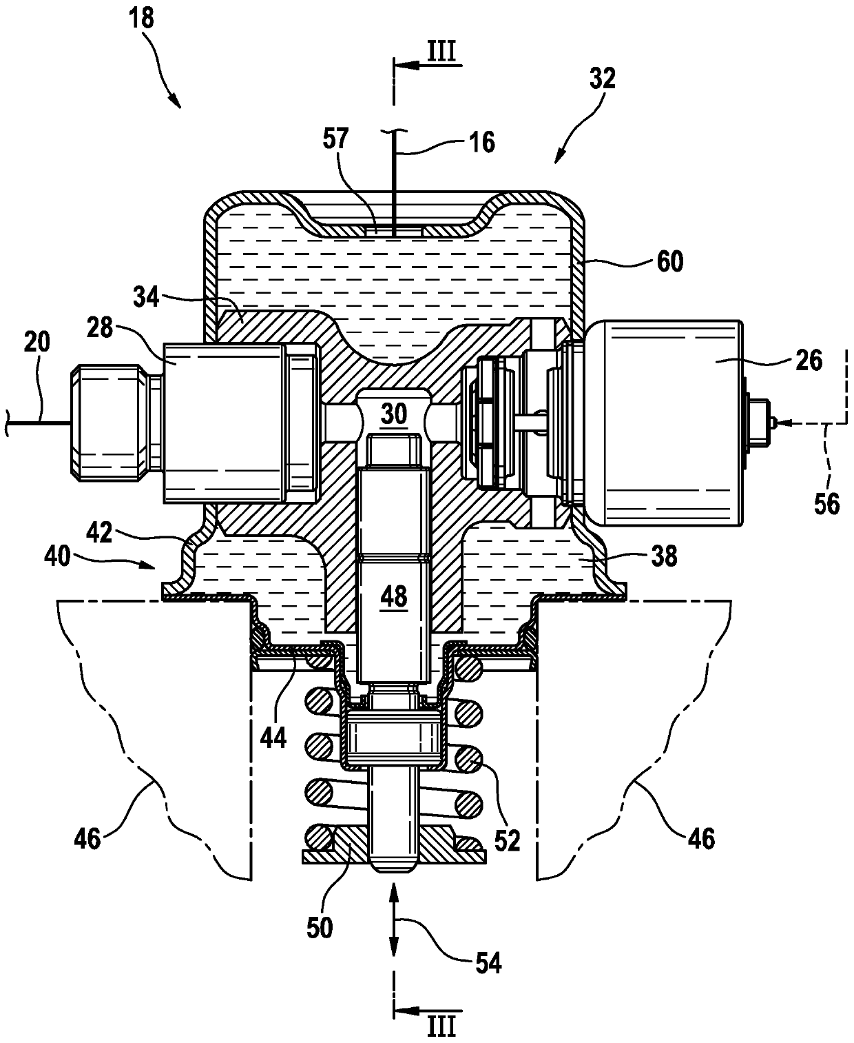
[0015] exist figure 1 , the fuel system of the internal combustion engine is generally designated with reference numeral 10 . The fuel system includes a fuel container 12 for receiving fuel. Connected to the fuel container 12 is an electric backing pump 14 . A low-pressure line 16 is again attached to the electric backing pump 14 . This low-pressure line leads to a high-pressure fuel pump 18 , which is generally indicated by a dash-dotted line and is designed in the exemplary embodiment in the form of a piston pump. A high-pressure line 20 leads from the high-pressure fuel pump to a fuel rail 22 . A plurality of injectors 24 are attached to the fuel rail 22 . A fuel delivery flow in fuel system 10 is directed from fuel container 12 to injector 24 .

[0016] The high-pressure fuel pump 18 comprises an inlet valve 26 embodied as a check valve and an outlet valve 28 embodied as a check valve, as well as a displacement chamber 30, which in the figure 1 are shown by known pum...


PUM

PropertyMeasurementUnit
Volumeaaaaaaaaaa
Wall thicknessaaaaaaaaaa
Volumeaaaaaaaaaa

Abstract

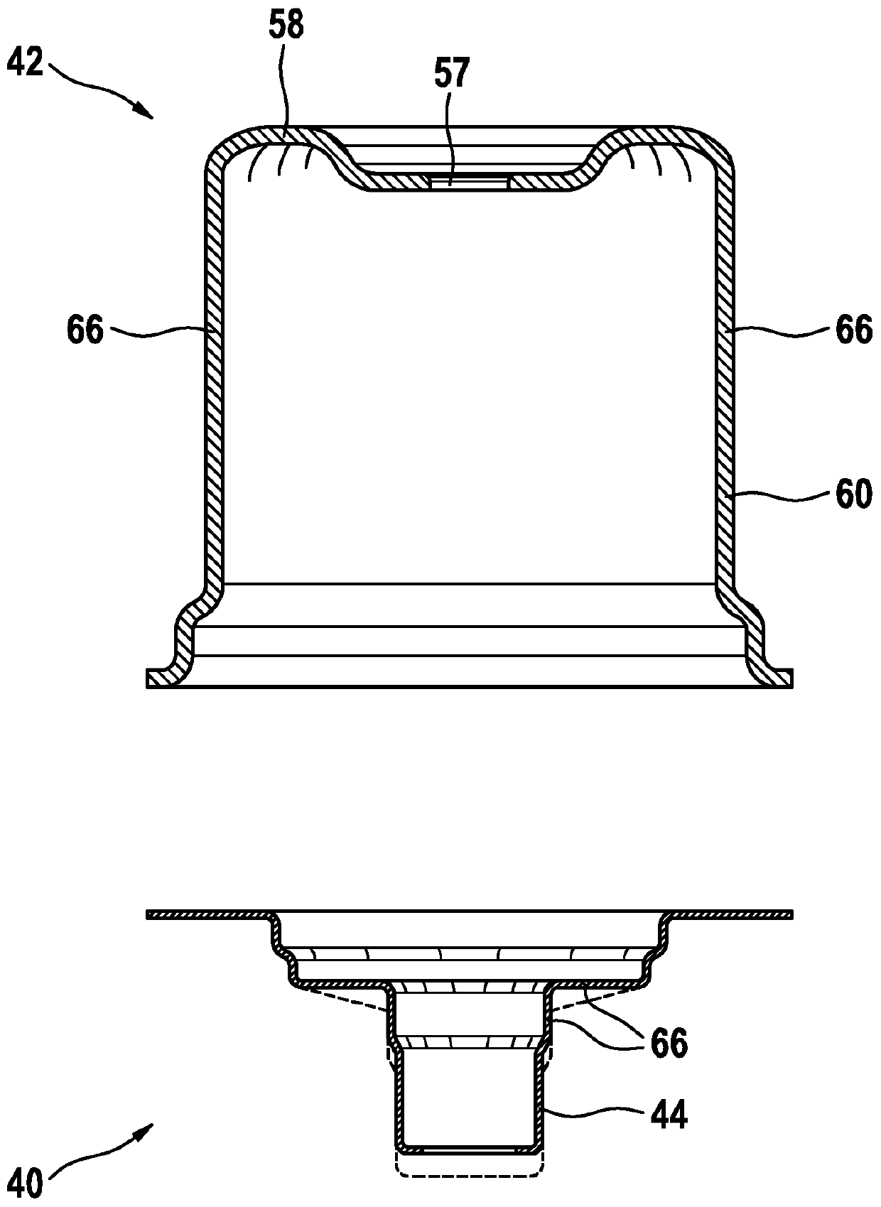
The invention relates to a high-pressure fuel pump comprising a housing wall of a pump housing (40) and a valve for damping pressure pulses on the inlet side by means of a change in the damping volume (38) by means of an elastically movable wall (66). Vibration damping device (32). It is proposed that at least a section of the elastically movable wall ( 66 ) is formed by at least a part of the sleeve region ( 60 ) of the housing wall and / or by at least a part of the sealing carrier ( 44 ), and , the section is configured in such a way that it makes at least a major contribution to the change in the damping volume ( 38 ).

Description

technical field [0001] The present invention relates to fuel high pressure pumps. Background technique [0002] Fuel systems for internal combustion engines are known on the market, in which fuel is delivered at high pressure from a fuel tank into a fuel rail by means of a backing pump and a mechanically driven high-pressure fuel pump. A pressure damper is usually arranged on or in the housing of such a high-pressure fuel pump. The pressure damper is usually arranged in the cover section of the housing which is connected to the low-pressure region and in which the gas-filled diaphragm capsule is arranged. The damping device serves to damp pressure pulses in the low-pressure region of the fuel system. Contents of the invention [0003] The problem underlying the invention is solved by the high-pressure fuel pump according to the invention. Describe the favorable improvement scheme in the application documents. Features which are essential to the invention are also found...

Claims


Application Information

Patent Timeline
IPC IPC(8): F02M59/10F02M59/44F02M55/04
CPCF02M55/04F02M59/102F02M59/44F02M59/48F02M2200/315F02M59/025F04B11/0091F04B19/22F04B53/10F04B53/14F04B53/16
Inventor S·芙洛O·阿尔布雷希特F·尼切T·阿尔盖尔J·科雷克A·普利施G·泰克
Owner ROBERT BOSCH GMBH
Learn More