

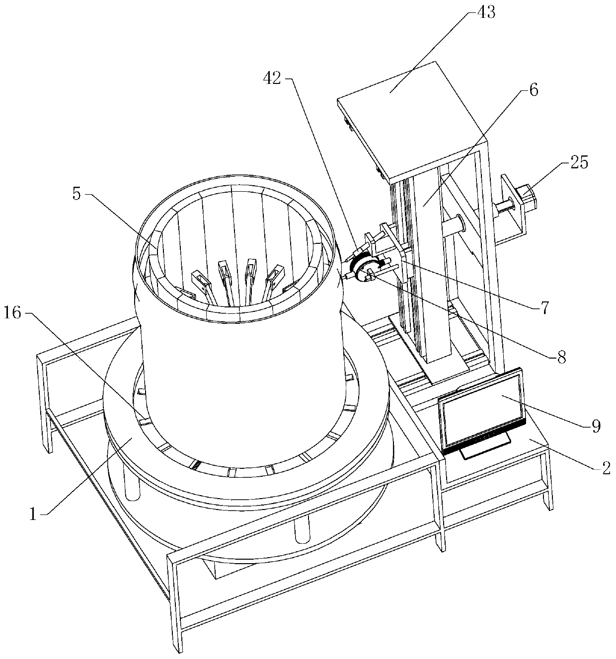
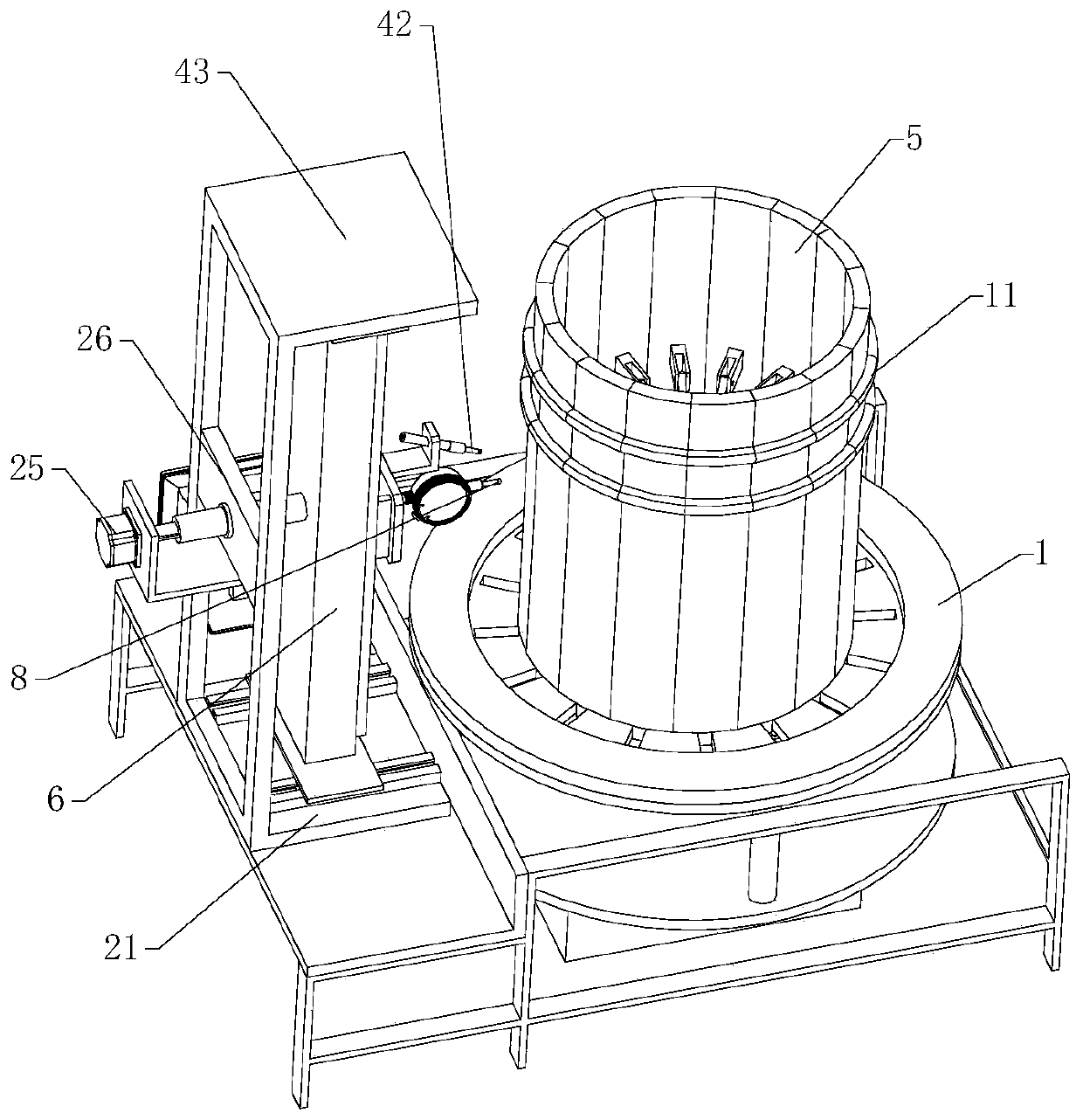
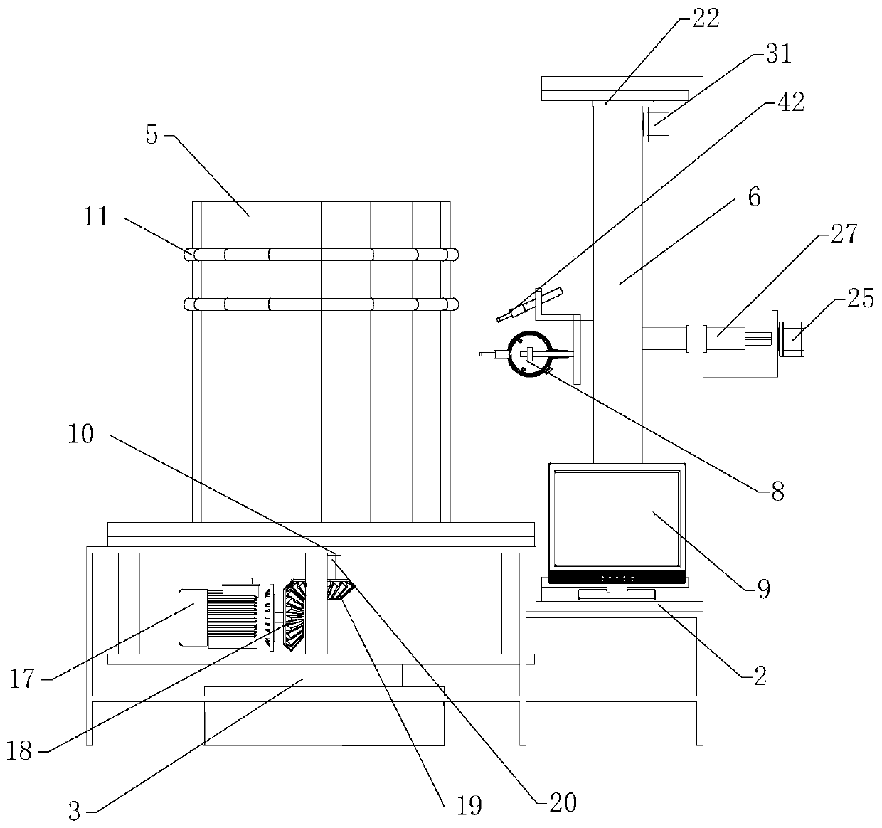
Barrel forming equipment with bounce value detecting and marking function and method thereof
A technology for detecting marks and forming equipment, which is applied in the direction of measuring devices, mechanical measuring devices, instruments, etc., which can solve the problems that the equipment cannot be detected, it is difficult to ensure the accuracy of the finished cylinder, and the accuracy of the cylinder is high.
- Summary
- Abstract
- Description
- Claims
- Application Information
AI Technical Summary
Problems solved by technology
Method used
Image

Examples
Embodiment Construction
[0032] In order to make the object, technical solution and advantages of the present invention clearer, the present invention will be further described in detail below in conjunction with the accompanying drawings and embodiments. It should be understood that the specific embodiments described here are only used to explain the present invention, not to limit the present invention.
[0033] In the description of the present invention, it should be noted that the terms "center", "upper", "lower", "left", "right", "front", "rear", "vertical", "horizontal", The orientation or positional relationship indicated by "inner", "outer", etc. is based on the orientation or positional relationship shown in the drawings, and is only for the convenience of describing the present invention and simplifying the description, rather than indicating or implying that the referred device or element must have Certain orientations, constructed and operative in certain orientations, therefore are not t...
PUM
 Abstract
Description
Claims
Application Information