A welding device for avoiding false soldering and poor contact during circuit board soldering

A technology of poor contact and welding device, applied in the direction of tin feeding device, welding equipment, auxiliary device, etc., to avoid excessive conveying and easy operation.

Active Publication Date: 2021-02-09
秦皇岛通宝光电科技有限公司
View PDF4 Cites 0 Cited by
  • Summary
  • Abstract
  • Description
  • Claims
  • Application Information

AI Technical Summary

Problems solved by technology

[0006] In order to solve the above problems, this example designs a welding device that avoids false welding and poor contact when soldering a circuit board. A welding device that avoids false welding and poor contact when soldering a circuit board in this example includes a pen holder. A transmission cavity is provided inside the pen holder, a fixed block is provided on the lower end surface of the transmission cavity, and a wall-touching device is provided between the fixed block and the transmission cavity, and the wall-touching device includes a sliding connection with the fixed block And extend to the push rod in the transmission cavity, the lower end of the push rod is connected to the contact wheel, the upper end of the push rod is provided with a slope push block, the contact wheel slides on the circuit board and is changed by the push rod The position of the inclined-plane push block, the transmission cavity is provided with an engaging device, and the engagement device includes a slide bar slidingly connected with the inner wall of the lower side of the transmission cavity, and a through groove is provided in the lower end of the slide bar. The inclined-plane clamping block slidingly connected with the inclined-plane pushing block in the through groove, the electric heating core is provided at the lower end of the sliding rod, and the sliding of the inclined-plane pushing block and the inclined-plane clamping block pushes the sliding rod to change the electric heating core The distance from the circuit board, the inner wall of the upper side of the transmission chamber is provided with an adjustment chamber, the adjustment chamber is slidably connected with the connecting rod fixedly connected with the sliding rod, and the connecting rod is provided with a The support plate at the outer end of the side, the upper end of the support plate is provided with a buckle device for fixing the tin bar, and the lower end of the support plate is provided with a conveying device for turning the tin bar and sending it in at an even speed. The conveying device includes a The connecting cavity on the support plate is rotatably connected with an up-and-down symmetrical drive shaft, and the drive shaft is provided with an I-shaped wheel, and the upper and lower two I-shaped wheels rotate in opposite directions to clamp the tin bar And horizontally sent to the lower end of the electric heating core to complete the soldering work, the upper side of the transmission chamber is equipped with a sensor

Method used


Image

  • A welding device for avoiding false soldering and poor contact during circuit board soldering
  • A welding device for avoiding false soldering and poor contact during circuit board soldering
  • A welding device for avoiding false soldering and poor contact during circuit board soldering

Examples


Embodiment Construction

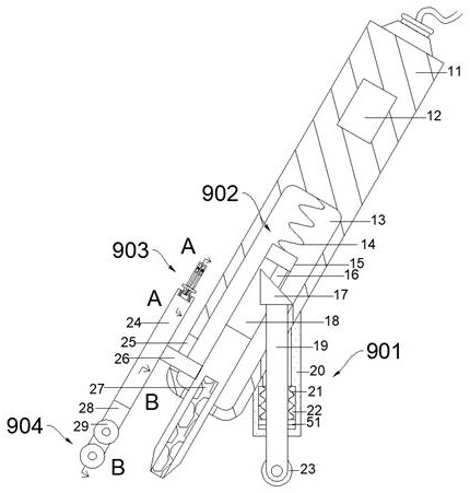
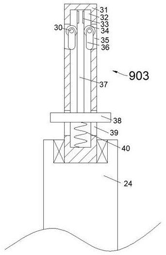
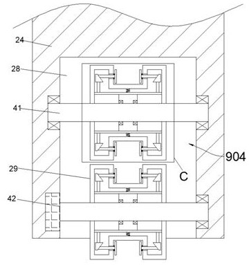
[0017] Combine below Figure 1-Figure 4 The present invention is described in detail, and for convenience of description, the orientations mentioned below are now stipulated as follows: figure 1 The up, down, left, right, front and back directions of the projection relationship itself are consistent.

[0018] The present invention relates to a soldering device for avoiding false soldering and poor contact during circuit board soldering. It is mainly used in the soldering process for avoiding false soldering and poor contact. The present invention will be further described below in conjunction with the drawings of the present invention:

[0019] A welding device for avoiding false soldering and poor contact during circuit board soldering according to the present invention includes a penholder 11, a transmission chamber 13 is provided inside the penholder 11, and a fixed block 20 is provided on the lower end surface of the transmission chamber 13 A wall-contacting device 901 is...


PUM


Abstract

The invention discloses a welding device for avoiding false soldering and poor contact when soldering a circuit board. The delivery point, the thermal melting point of the tin bar, and the contact point with the circuit board move synchronously among the three points, avoiding the change of the distance between the contact iron and the circuit board when the force exerted by the hand cannot maintain a stable value. As a result, poor contact occurs. At the same time, the tin bar is conveyed in an active and uniform manner to avoid the false soldering phenomenon of connecting multiple soldering points together when the tin bar is transported too much. In addition, freeing one hand can facilitate the use of other auxiliary tools. , the operation is more convenient.

Description

technical field [0001] The invention relates to the technical field of circuit board production, in particular to a soldering device for avoiding false soldering and poor contact during circuit board soldering. Background technique [0002] The circuit board has many solder points for connecting electronic components. The traditional soldering method is to place the circuit board on a plane, then hold the tin bar in the left hand and the electric soldering iron in the right hand, melt the material and connect it to the gap to complete the soldering work. [0003] However, because the soldering points on the circuit board may be too small, and if there are too many tin bars, other irrelevant points will be soldered, so that the circuit cannot be operated due to false soldering, and it may also be caused by the gap between the head of the electric soldering iron and the board. The distance between them is too long, resulting in poor contact. The present invention illustrates...

Claims


Application Information

Patent Timeline
Patent Type & Authority Patents(China)
IPC IPC(8): H05K3/34B23K3/06B23K3/08
CPCB23K3/06B23K3/0607B23K3/063B23K3/08H05K3/34
Inventor 不公告发明人
Owner 秦皇岛通宝光电科技有限公司
Why Eureka
Try Eureka