Tool module for textile machines

A tool module and tool technology, applied in textiles and papermaking, knitting, warp knitting, etc., can solve problems such as unfavorable machines, and achieve the effects of improving cooling, reducing heat increase, and increasing heat dissipation

Pending Publication Date: 2020-06-05
GROZ BECKERT KG
View PDF10 Cites 0 Cited by
  • Summary
  • Abstract
  • Description
  • Claims
  • Application Information

AI Technical Summary

Problems solved by technology

This can lead to longitudinal extension of the rod, which can be detrimental to the operation of the machine, especially in tufting and warp knitting machines

Method used


Image

  • Tool module for textile machines
  • Tool module for textile machines
  • Tool module for textile machines

Examples


Embodiment Construction

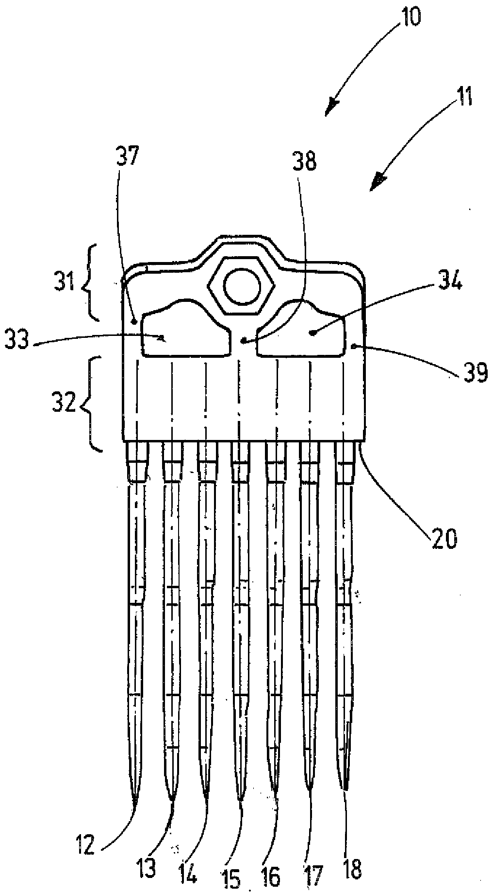
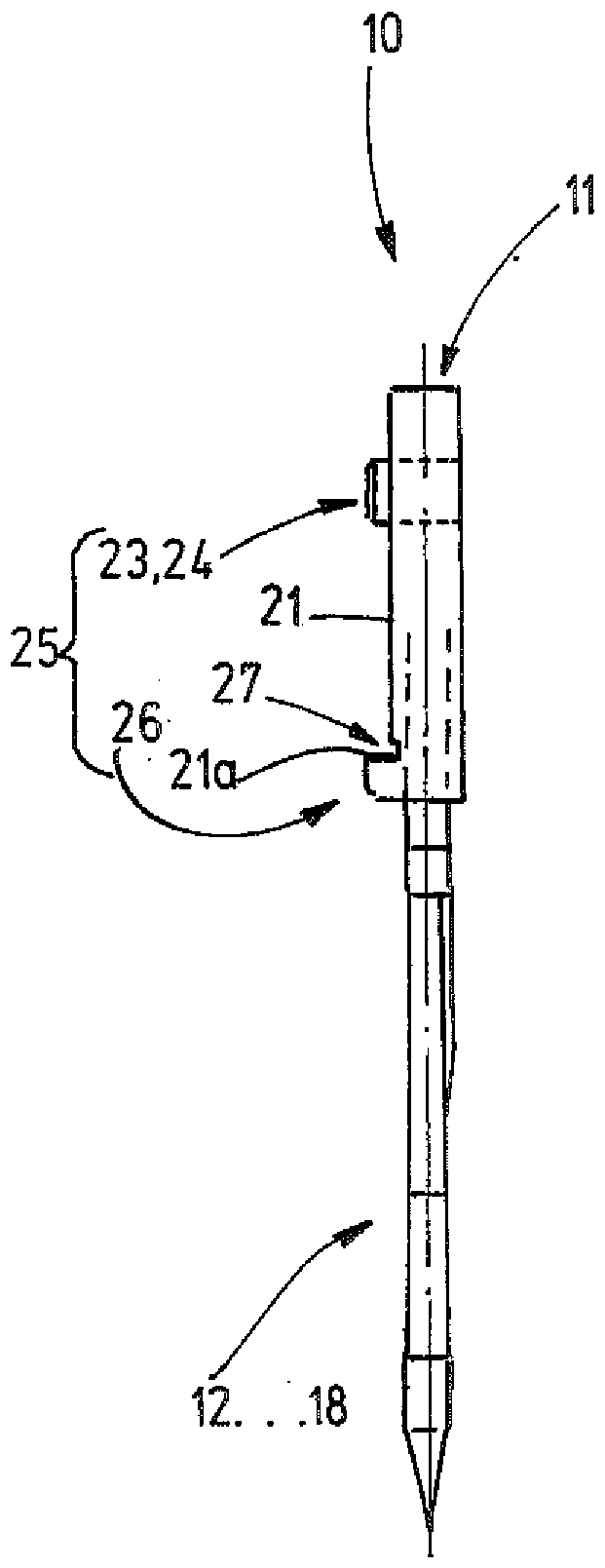
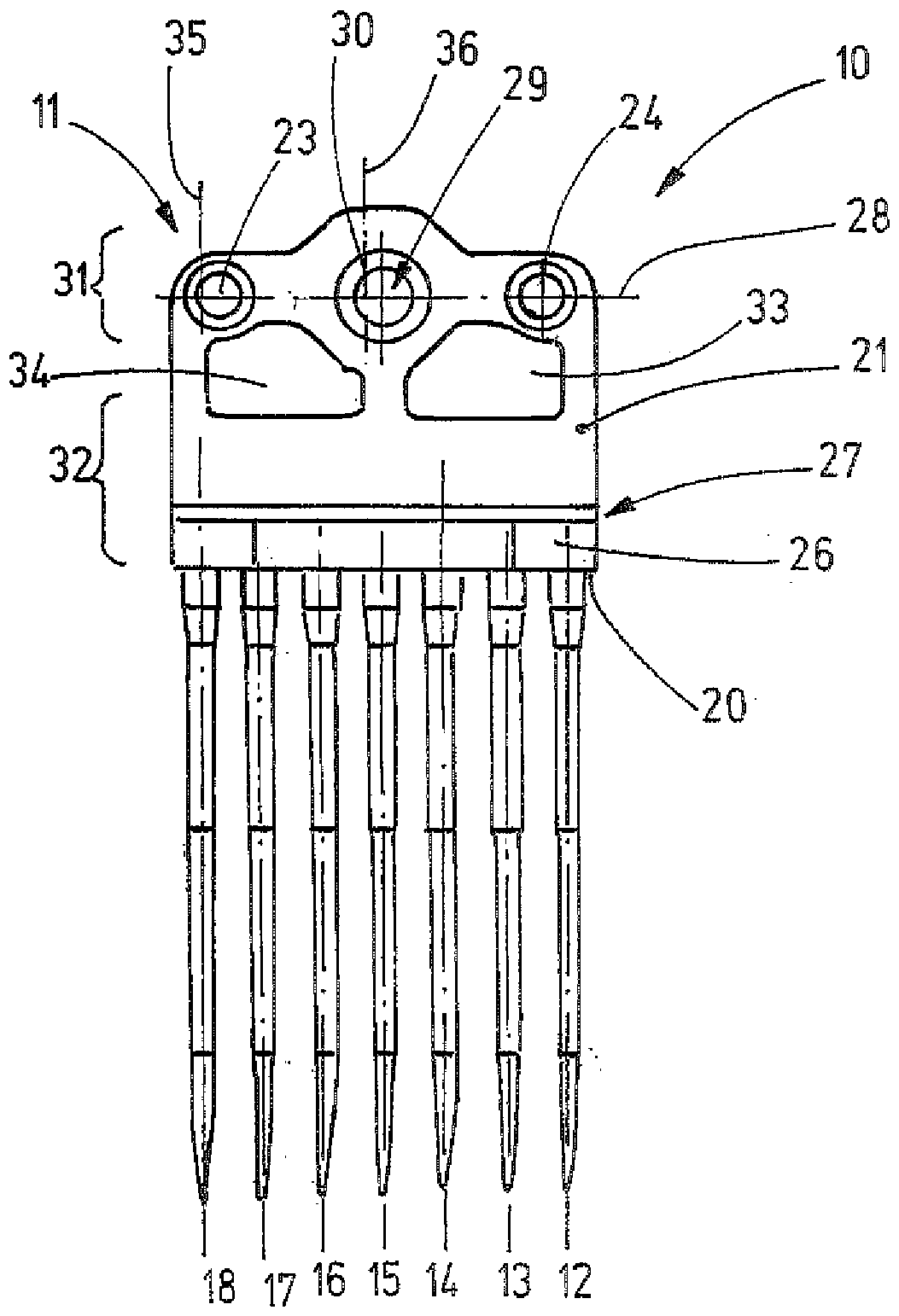
[0023] exist figure 1 In FIG. 1 , a tool module 10 is shown for illustrative purposes only to illustrate features of the invention, comprising a module body 11 and tools 12 - 18 retained at the module body. Tufting needles are exemplarily shown as tools. Similarly, however, other tools such as guide pins, grippers, fingers, knives, etc. may be provided that operate in parallel in synchronization with each other. Independently thereof, the tools 12 - 18 are arranged parallel to one another and are fastened with their respective shank ends at the module body 12 . As an example, 7 tools are shown. However, any other desired number and singular number of tools may be provided at the module body 11 .

[0024] The module body 11 is preferably formed of metal, in particular zinc alloy, zinc aluminum alloy or another metal alloy which melts at a temperature below 1000°C. In particular, the module body 11 may be formed as a die-cast body.

[0025] The module body 11 has the form o...


PUM


Abstract

The invention relates to a tool module (10) having a module body (11), which has a contact surface (21) and an orienting structure (22). A fastening opening (29) and additionally at least one, preferably a plurality of additional openings (33, 34) extend through the contact surface (21). The area of one additional opening (33) or (34) is larger than, preferably considerably larger than, for example at least twice or three times as large as the cross-sectional area of the fastening opening (29). Thus, a module body (11) is provided, by means of which an increased operating speed of the textilemachine can be achieved.

Description

technical field [0001] The invention relates to a tool module for a textile machine, in particular for tufting applications. [0002] In particular, the invention relates to a tool module for fastening at the bar of a textile machine, for example a tufting machine or also a warp knitting machine. Background technique [0003] The bars of the tufting or warp knitting machines are provided with a multitude of tools (eg grippers, needles, guide pins, knives, etc.) gathered by forming groups in modules. Each module includes a base body into or at which a number of tools are attached. In order to equip the rod with the tool, the module is connected to the rod. [0004] This principle can be derived from DE 4223642 C2, DE 4411277 A1, US 5947942. Thereby, the module body is generally provided with a form-fit structure which simplifies the positioning of each module in a correct positional arrangement at the rod. [0005] Furthermore, a module is known from DE 19928885 C1 which ...

Claims


Application Information

Patent Timeline
Patent Type & Authority Applications(China)
IPC IPC(8): D05C15/20
CPCD05C15/20D04B27/06D05C15/10
Inventor A.帕斯
Owner GROZ BECKERT KG
Why Eureka
Try Eureka