
A multi-level mems optical switch unit and optical cross device

An optical switch and optical crossover technology, applied in the field of optical communication, can solve the problems of complex control part, limited switching speed, and affecting the switching time of the micro-mirror state.

Active Publication Date: 2022-02-25
HUAWEI TECH CO LTD
View PDF5 Cites 0 Cited by
  • Summary
  • Abstract
  • Description
  • Claims
  • Application Information

AI Technical Summary

Problems solved by technology

Seriously affects the state switching time of the micromirror, resulting in the limitation of the switching speed of OXC based on 3D analog MEMS, which is limited by the switching speed of MEMS
[0009] In addition, the MEMS structure provided by the existing technology is an analog MEMS, and there are still problems in the control mechanism and driving structure that are quite complicated. Its working mode is analog, so the control circuit needs to be able to accurately control the voltage applied to the electrodes to control the micromirror. The deflection state, the control part is complicated, and the cost is high

Method used


Image

  • A multi-level mems optical switch unit and optical cross device
  • A multi-level mems optical switch unit and optical cross device
  • A multi-level mems optical switch unit and optical cross device

Examples


Embodiment Construction

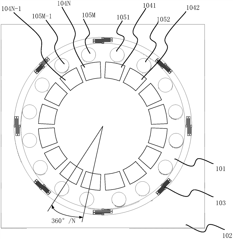
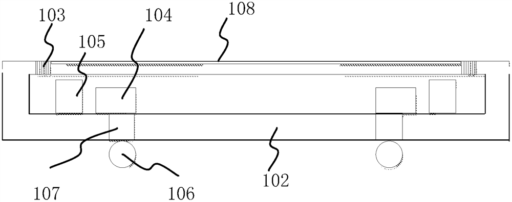
[0036] The embodiment of the present application provides a multi-level MEMS optical switch unit and an optical cross-connect device, which can realize a multi-level digital optical switching engine and simplify the control of the deflection state of the micro-control mirror.

[0037] Embodiments of the present application are described below in conjunction with the accompanying drawings.

[0038] The terms "first", "second" and the like in the specification and claims of the present application and the above drawings are used to distinguish similar objects, and are not necessarily used to describe a specific sequence or sequence. It should be understood that the terms used in this way can be interchanged under appropriate circumstances, and this is merely a description of the manner in which objects with the same attribute are described in the embodiments of the present application. Furthermore, the terms "comprising" and "having", as well as any variations thereof, are inten...


PUM


Abstract

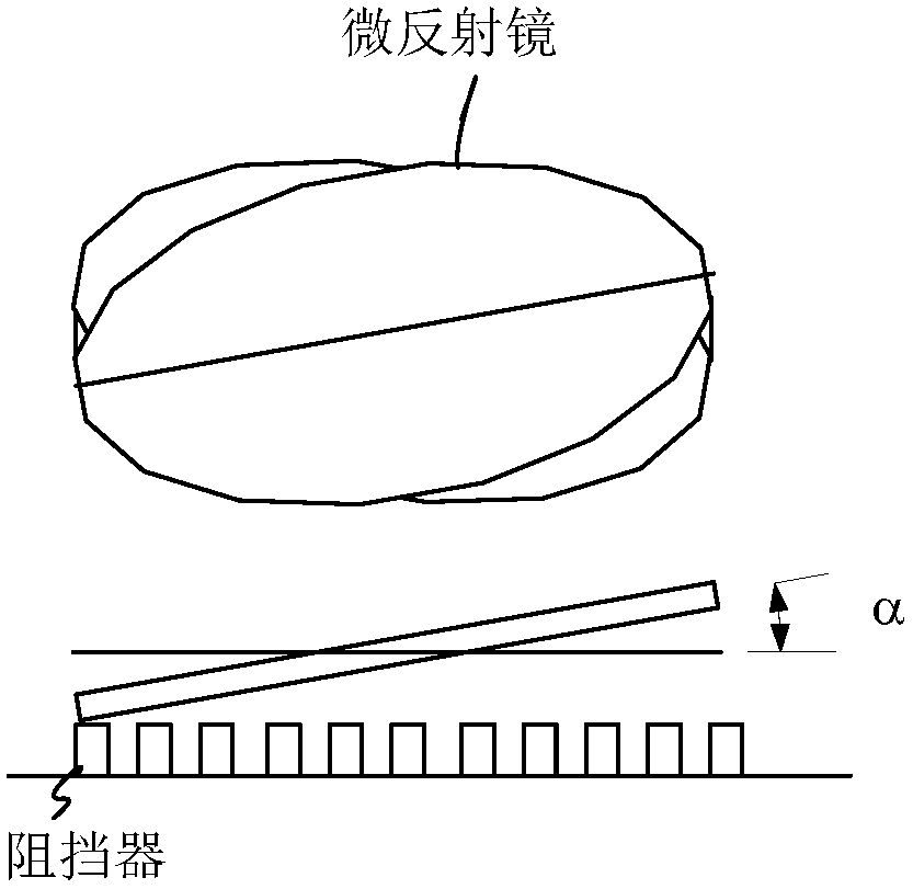
A multilevel MEMS optical switch unit and an optical cross device. In the multi-level MEMS optical switch unit, the micro-mirror is movably connected to the substrate through the cantilever beam; When at least one of the electrodes generates a force, the micro-mirror is in the target deflection state; when the force is zero, the micro-mirror is restored to the initial state; a cavity space is formed between the micro-mirror and the substrate, N electrodes and The M stoppers are arranged in the cavity space, and the N electrodes and the M stoppers are fixed on the substrate; at least one of the N electrodes is used to generate force and control the micromirror into a deflection state; the micromirror , is used to enter the deflection state under the force of at least one electrode in the N electrodes; at least one blocker in the M blockers is used to block the micro-mirror, so that the micro-mirror stops to the target deflection state.

Description

technical field [0001] The embodiments of the present application relate to the field of optical communication, and in particular to a multi-level micro-electro-mechanical system (Micro-Electro-Mechanical System, MEMS) optical switch unit and an optical cross-connect device. Background technique [0002] In recent years, with the development of optical switch technology and the large-scale application of WDM (Wavelength Division Multiplex, WDM), the capacity of optical network node equipment is increasing, which puts forward higher requirements for the survivability of the network. Cross-connect (Optical Cross-connect, OXC) integrates transmission and switching, with large transmission capacity, flexible networking, scalable and reconfigurable network, easy to upgrade, and transparent transmission of different speed levels in various formats It is an important node device that constitutes an optical transport network (Optical Transport Network, OTN). [0003] The key to rea...

Claims


Application Information

Patent Timeline
Patent Type & Authority Patents(China)
IPC IPC(8): G02B26/08
CPCG02B6/3584G02B6/3518G02B6/357G02B6/32G02B26/0841G02B26/08
Inventor 闫云飞赵晗冯志勇邹冰
Owner HUAWEI TECH CO LTD
Learn More