Rubber band vulcanization device with rapid cooling function

A rapid cooling and rubber band technology, which is applied in the field of rubber band processing equipment, can solve the problems of incomplete vulcanization, difficulty in ensuring the stacking effect of rubber bands, and inability to guarantee the cooling effect of rubber band vulcanization, so as to improve the vulcanization effect and ensure the vulcanization quality. Effect

Inactive Publication Date: 2020-06-09
安徽省潜山市创先实业有限公司
View PDF5 Cites 1 Cited by
  • Summary
  • Abstract
  • Description
  • Claims
  • Application Information

AI Technical Summary

Problems solved by technology

[0006] Aiming at the deficiencies of the prior art, the present invention provides a rubber band vulcanizing device with rapid cooling function, which overcomes the deficiencies of the prior art, has a reasonable design and a compact structure, and aims to solve the problem of vulcanization after the existing vulcanization equipment is put into operation after transformation. The stacking effect of rubber bands is difficult to guarantee, and the vulcanization is not complete; the vulcanization effect of rubber bands and the cooling after vulcanization cannot be guaranteed

Method used


Image

  • Rubber band vulcanization device with rapid cooling function
  • Rubber band vulcanization device with rapid cooling function
  • Rubber band vulcanization device with rapid cooling function

Examples


Embodiment 1

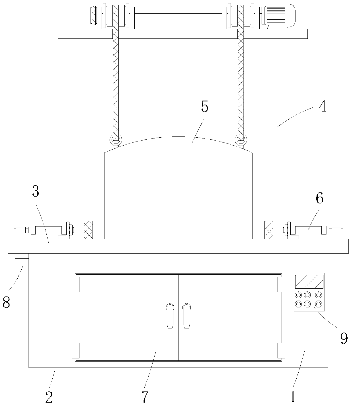
[0039] A rubber band vulcanizing device with rapid cooling function, comprising a base box 1 and a plurality of support feet 2 installed at the lower end of the base box 1, a processing table 3 is installed horizontally on the upper end of the base box 1, and a processing table 3 is provided on the upper end of the processing table 3 The vulcanization bottom tank, and the vulcanization mechanism 8 is arranged in the vulcanization bottom tank, and the top of the vulcanization bottom tank is matched with an inverted bowl-shaped vulcanization shell cover 5, and the vulcanization shell cover 5 goes down to cooperate with the vulcanization bottom tank to form a complete vulcanization chamber. For the vulcanization of rubber bands, it can be understood that the lower end of the vulcanization shell upper cover 5 can be provided with a sealing rubber ring to ensure the sealing of the vulcanization chamber;

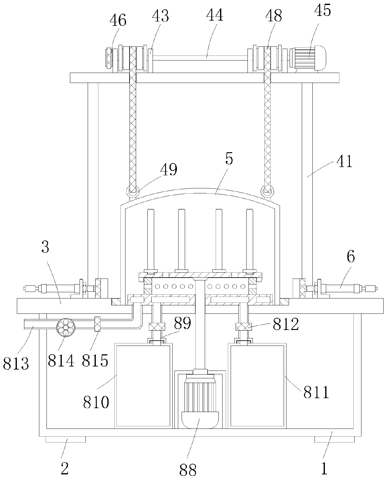
[0040] In this example, if Figure 2-6 As shown, the vulcanization mechanism ...

Embodiment 2

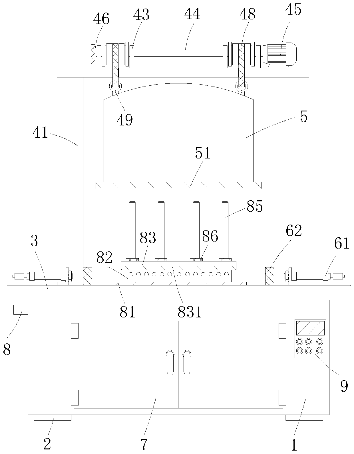
[0051] The difference between this embodiment and embodiment 1 is that, as Figure 1-3 As shown in and 7, a lifting mechanism 4 is also provided above the vulcanization shell upper cover 5, the lifting mechanism 4 includes a frame 41 installed on the upper end of the processing table 3, and the top wall of the frame 41 is distributed in a matrix with four Winch 43, winch 43 is installed on the top wall of frame 41 by turret 42, is positioned at two winches 43 on the same side and is coaxially connected in series by turning bar 44, and one end of two turning bars 44 is all equipped with drive chain wheel 46, And two transmission sprockets 46 are connected by chain 47 transmissions, and the shaft end of one of them rotating rod 44 is installed on the output end of servomotor 45, and servomotor 45 is fixedly installed on the top wall of frame 41, winds on winch 43 There are ropes 48, and the lower ends of the four ropes 48 extend to the inside of the frame 41 and are connected wi...

Embodiment 3

[0055] The difference between this embodiment and Embodiment 1 is that, as shown in Figures 3 and 8, a positioning mechanism 6 is symmetrically provided on both sides of the vulcanization bottom groove, and the positioning mechanism 6 includes a positioning block 62 that is symmetrically slidably installed on the upper end of the processing table 3 , and the opposite side of the positioning block 62 is installed on the telescopic end of the positioning cylinder 61, and the positioning cylinder 61 is installed on the upper end of the processing table 3 through a bracket.

[0056] In this example, if Figure 3-4 As shown, the lower edge of the upper cover 5 of the vulcanization shell is integrally formed with an annular rib 51 outward, and a positioning groove is provided at the position below the vulcanized bottom groove matching the annular rib 51 .

[0057] According to the rubber band vulcanizing device with rapid cooling function of the above-mentioned embodiment of the pre...


PUM


Abstract

The invention relates to the technical field of rubber band processing equipment, and provides a rubber band vulcanization device with a rapid cooling function. The device aims to solve the problem that a rubber band stacking effect is difficult to guarantee after existing vulcanization equipment is transformed and put into production, vulcanization is incomplete, and the vulcanization effect of rubber bands and cooling after vulcanization is completed cannot be guaranteed. The device comprises a base box and a plurality of supporting legs installed at the lower end of the base box, a machining table board is horizontally installed at the upper end of the base box, a vulcanization bottom groove is formed in the upper end of the machining table board, a vulcanizing mechanism is arranged inthe vulcanization bottom groove, a inverted bowl-shaped vulcanizing shell upper cover is arranged above the vulcanization bottom groove in a matched mode, the vulcanizing mechanism comprises a gas conveying disc installed in the vulcanization bottom groove, the gas conveying disc is of an internal hollow structure, and two communicating pipes are arranged at the lower end of the gas conveying discin a penetrating mode. The device is particularly suitable for high-quality vulcanization of the rubber bands, and has high social usage value and application prospect.

Description

technical field [0001] The invention relates to the technical field of rubber band processing equipment, in particular to a rubber band vulcanizing device with a rapid cooling function. Background technique [0002] Rubber band is a short loop made of rubber and latex, which is mainly used for binding items. It has the characteristics of high elongation, good resilience, low price, and convenient use. Its manufacturing process includes dipping, vulcanization, demoulding, ring cutting (strip) and other processes. [0003] The vulcanization of rubber bands is generally after the raw materials are extruded into rubber sheaths, vulcanized first, and then cut into rings to form them. The vulcanization effect of rubber bands is poor. At present, it is also proposed to cut the rings first and then vulcanize. After the existing vulcanization equipment is transformed and put into production, the effect is not satisfactory. The reasons include: first, during vulcanization, the stack...

Claims


Application Information

Patent Timeline
Patent Type & Authority Applications(China)
IPC IPC(8): B29C35/00B29C35/04B29C35/16
CPCB29C35/002B29C35/049B29C35/16B29C2035/1683
Inventor 杜传来邹儒平田五四
Owner 安徽省潜山市创先实业有限公司
Why Eureka
Try Eureka