
Hydraulic control circuit and method used for injection machine and capable of realizing high-speed and high-precision injection

A control circuit and injection molding machine technology, applied in the field of injection molding machines, can solve the problems of limited flow rate of a single plate servo valve, poor return accuracy of the circuit, high response requirements, etc., to achieve improved brake response, fast injection response, and accurate positioning Effect

Active Publication Date: 2020-06-09
HAITIAN PLASTICS MACHINERY GRP
View PDF6 Cites 2 Cited by
  • Summary
  • Abstract
  • Description
  • Claims
  • Application Information

AI Technical Summary

Problems solved by technology

Disadvantages: 1. The flow rate of a single plate-type servo valve is limited, and the response of a large-size plate-type servo valve to a smaller-size valve is obviously insufficient. For injection processes that require high-precision injection and high response requirements, or require large flow rates, this The shortcomings of similar control loops are obvious
2. Since the servo valve only controls the injection accuracy, the ejection accuracy of this type of circuit is poor

Method used


Image

  • Hydraulic control circuit and method used for injection machine and capable of realizing high-speed and high-precision injection

Examples


Embodiment Construction

[0020] The following are specific embodiments of the present invention and in conjunction with the accompanying drawings, the technical solutions of the present invention are further described, but the invention is not limited to these embodiments.

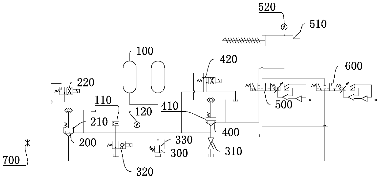
[0021] Such as figure 1 As shown, a high-speed and high-precision injection molding machine hydraulic control circuit is characterized in that it includes: an accumulator 100, a liquid filling control valve group 200, a pressure relief valve group 300, a liquid discharge control valve group 400, and a control valve for the injection molding machine. The first servo valve 500 for the injection cavity and the second servo valve 600 for controlling the ejection cavity of the injection molding machine, and the pressure relief valve group 300 are used to release the pressure of the accumulator during the working process and after it stops working to prevent its pressure from being too high When a dangerous event occurs, the filling con...


PUM


Abstract

The invention discloses a hydraulic control circuit and method used for an injection machine and capable of realizing high-speed and high-precision injection, and belongs to the technical field of injection machines. By the adoption of the hydraulic control circuit and method, the problems that an existing hydraulic control circuit of the injection machine is poor in injection precision and ejection precision and slow in response and cannot realize accurate positioning are solved. The hydraulic control method used for the injection machine and capable of realizing high-speed and high-precisioninjection comprises the following steps that when injection is carried out by the injection machine, pressure oil reaches a liquid charging control valve bank through a port, the liquid charging control valve bank controls the pressure oil to carry out liquid charging on an energy accumulator, the pressure oil in the energy accumulator reaches a first servo valve through a liquid discharging valve bank, the first servo valve controls the pressure oil to enter an injection cavity of the injection machine according to a pressure or flow rate set by an injection machine system, a second servo valve is opened, and the pressure oil in the injection cavity of the injection machine enters an oil tank through the second servo motor. The pressure and flow rate in the injection cavity and the pressure and flow rate in an ejection cavity are controlled separately, so that the speed of brake response during high-speed injection is increased, the injection response is made quicker, and positioningis more accurate.

Description

technical field [0001] The invention relates to the technical field of injection molding machines, in particular to an injection molding machine hydraulic control circuit and method for high-speed and high-precision injection. Background technique [0002] With the increasing demand of injection molding machines for high-speed and high-precision injection, the conventional injection circuit uses an accumulator + a single plate servo valve to control the hydraulic circuit of the two chambers of the injection cylinder. Shoot back to provide power. A single servo valve synchronously controls the oil inlet and outlet of the injection cylinder. This circuit can meet the vast majority of production needs. Disadvantages: 1. The flow rate of a single plate-type servo valve is limited, and the response of a large-size plate-type servo valve to a smaller-size valve is obviously insufficient. For injection processes that require high-precision injection and high response requirements...

Claims


Application Information

Patent Timeline
IPC IPC(8): B29C45/82
CPCB29C45/82
Inventor 郑海伟方钱张旭峰周兴刚戚科峰
Owner HAITIAN PLASTICS MACHINERY GRP
Features
  • Generate Ideas
  • Intellectual Property
  • Life Sciences
  • Materials
  • Tech Scout
  • Unparalleled Data Quality
  • Higher Quality Content
  • 60% Fewer Hallucinations
Learn More