Straw briquetting machine material receiving table capable of vibrating

A technology of straw briquetting machine and material receiving platform, which is applied in the direction of material forming press, press, fuel, etc., and can solve the problems of reducing production efficiency, manual cleaning, time-consuming and laborious, etc.

Active Publication Date: 2020-06-09
台州壹品工业设计有限公司
View PDF7 Cites 1 Cited by
  • Summary
  • Abstract
  • Description
  • Claims
  • Application Information

AI Technical Summary

Problems solved by technology

[0002] As a straw processing equipment, the straw briquetting machine presses the straw into block fuel, which is convenient for transportation and can also improve the combustion efficiency. However, when the straw briquetting machine is working, the material at the extrusion port is easy to accumulate on the receiving table, which is difficult Sliding down, forming a large area of ​​accumulation, when the pile of material is too high, it will affect the extrusion of the material at the extrusion port. At the same time, the accumulated material needs to be cleaned manually, which is time-consuming and laborious, and reduces the production efficiency. Therefore, we propose A vibrating straw briquetting machine receiving platform to solve the above problems

Method used


Image

  • Straw briquetting machine material receiving table capable of vibrating
  • Straw briquetting machine material receiving table capable of vibrating
  • Straw briquetting machine material receiving table capable of vibrating

Examples


Embodiment Construction

[0017] The following will clearly and completely describe the technical solutions in the embodiments of the present invention with reference to the accompanying drawings in the embodiments of the present invention. Obviously, the described embodiments are only some, not all, embodiments of the present invention. Based on the embodiments of the present invention, all other embodiments obtained by persons of ordinary skill in the art without making creative efforts belong to the protection scope of the present invention.

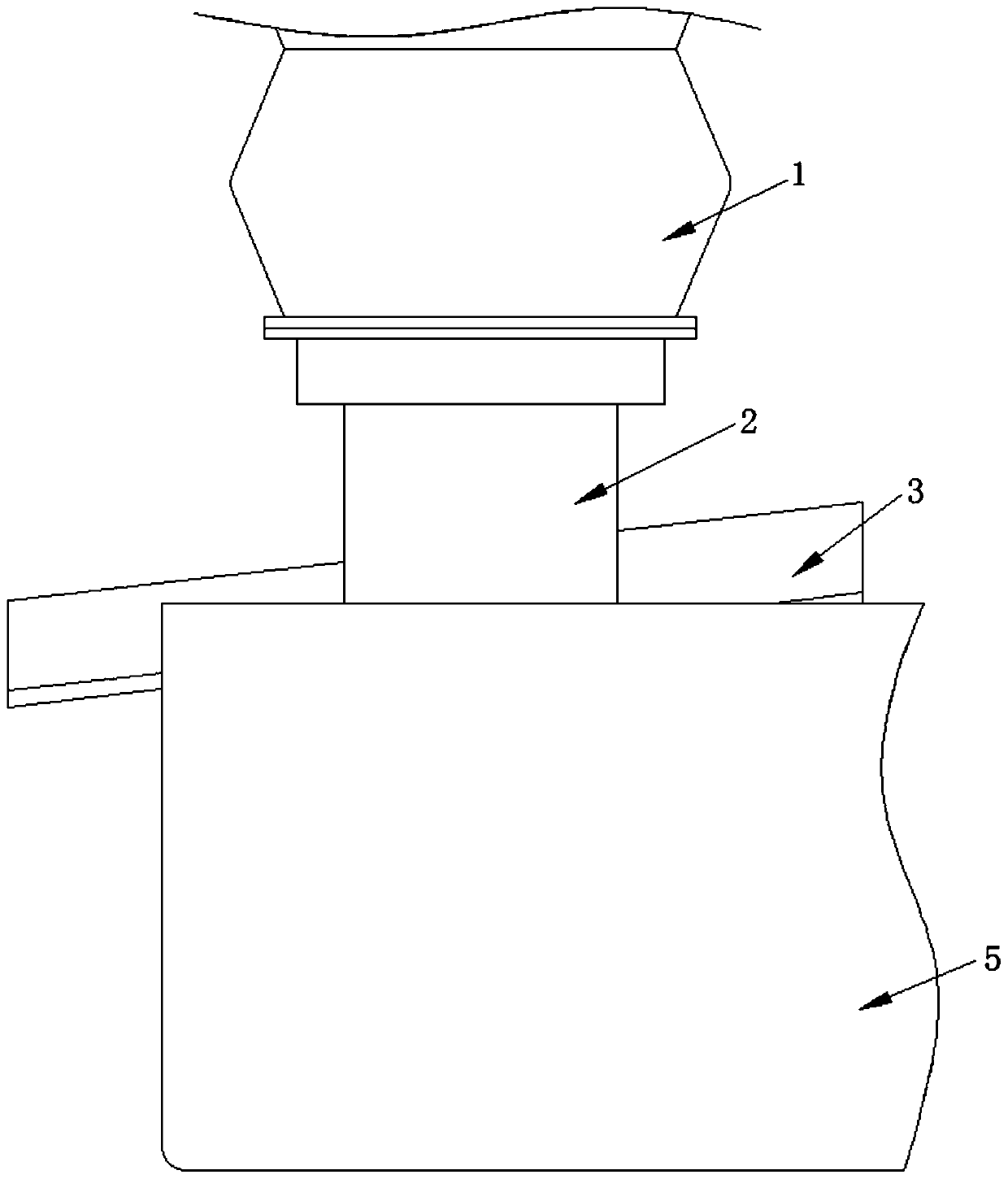
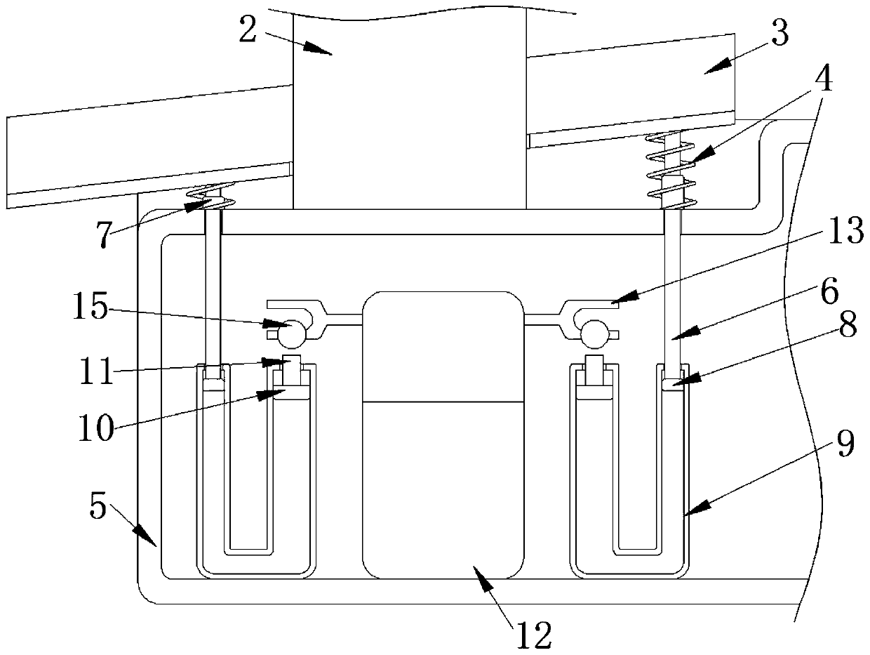
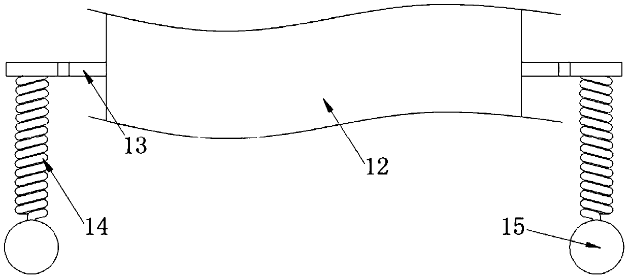
[0018] see Figure 1-3 , a vibrating straw briquetting machine material receiving platform, including a pressure roller 1, a main shaft 2, a material receiving platform 3, a spring 4, a frame 5, a movable rod 6, a fixed sleeve 7, a piston 8, a different diameter U-shaped pipe 9, piston 2 10, movable rod 2 11, motor 12, tuning fork 13, spring 2 14 and briquetting block 15, pressure roller 1 plays the role of extruding material, and the bottom of pressure roller...


PUM


Abstract

The invention discloses a straw briquetting machine material receiving table capable of vibrating. The straw briquetting machine material receiving table comprises a compression roller, a main shaft,a material receiving table, a first spring, a rack, a first movable rod, a fixing sleeve, a first piston, an abnormal-diameter U-shaped pipe, a second piston, a second movable rod, a motor, a tuning fork, a second spring and a pressing block. According to the straw briquetting machine material receiving table capable of vibrating, the tuning fork and the first movable rod are cooperated; when thestraw briquetting machine works, the motor vibrates, the vibration of the motor is transferred to the tuning fork, the tuning fork vibrates and drives the pressing block to vertically vibrate, and thepressing block beats the second movable rod; through the function of the abnormal-diameter U-shaped pipe, the first movable rod upwards moves to upwards support the material receiving table; when thematerial receiving table moves to a highest point, the material receiving table downwards moves due to the function of gravity; through one series of transmission, the second movable rod rises, and when the second movable rod rises to a certain height, the pressing block can beat the second movable rod; finally, the above action is carried out back and forth, the material receiving table carriesout vertical reciprocating vibration, and an effect of vibration can be achieved.

Description

technical field [0001] The invention relates to the technical field of a material receiving platform of a straw briquetting machine, in particular to a vibrating material receiving platform of a straw briquetting machine. Background technique [0002] As a straw processing equipment, the straw briquetting machine presses the straw into block fuel, which is convenient for transportation and can also improve the combustion efficiency. However, when the straw briquetting machine is working, the material at the extrusion port is easy to accumulate on the receiving table, which is difficult Sliding down, forming a large area of ​​accumulation, when the pile of material is too high, it will affect the extrusion of the material at the extrusion port. At the same time, the accumulated material needs to be cleaned manually, which is time-consuming and laborious, and reduces the production efficiency. Therefore, we propose A vibrating material receiving platform of a straw briquette m...

Claims


Application Information

Patent Timeline
IPC IPC(8): B30B11/00B30B15/32C10L5/44
CPCB30B11/00B30B15/32C10L5/445C10L2290/32Y02E50/10Y02E50/30
Inventor 余雪飘
Owner 台州壹品工业设计有限公司
Why Eureka
Try Eureka