
Silk-screen feeding and discharging device

A screen printing and equipment technology, applied in the field of screen printing loading and unloading equipment, can solve the problems of semi-automatic screen printing equipment being idle, manpower occupation, and expensive

Pending Publication Date: 2020-06-09
XIAMEN HONGXIN ELECTRON TECH +1
View PDF0 Cites 23 Cited by
  • Summary
  • Abstract
  • Description
  • Claims
  • Application Information

AI Technical Summary

Problems solved by technology

[0002] In the production process of flexible circuit boards, silk screen printing technology is often required to print character ink, resist ink, etc. for flexible circuit board products. Due to the thin and soft characteristics of flexible circuit boards, the current operation method mainly relies on manual operation of semi-automatic screen printing machines. It is completed by one machine, and one person operates one screen printing machine, which takes a lot of manpower
Although there are some fully automatic screen printing machines on the market, they are expensive, and most factories have purchased multiple semi-automatic screen printing machines in the early stage. If new automatic screen printing equipment is introduced, the existing semi-automatic screen printing equipment may be left idle. Utilize the existing resources to realize the automation of the silk screen printing process to save manpower, it is necessary to upgrade the existing semi-automatic screen printing machine
[0003] In view of this, the designer aimed at the many defects and inconveniences caused by the imperfect structural design of the existing semi-automatic screen printing machine, and actively researched and improved the trial production to develop and design the present invention.

Method used

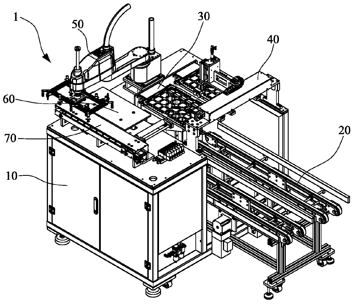
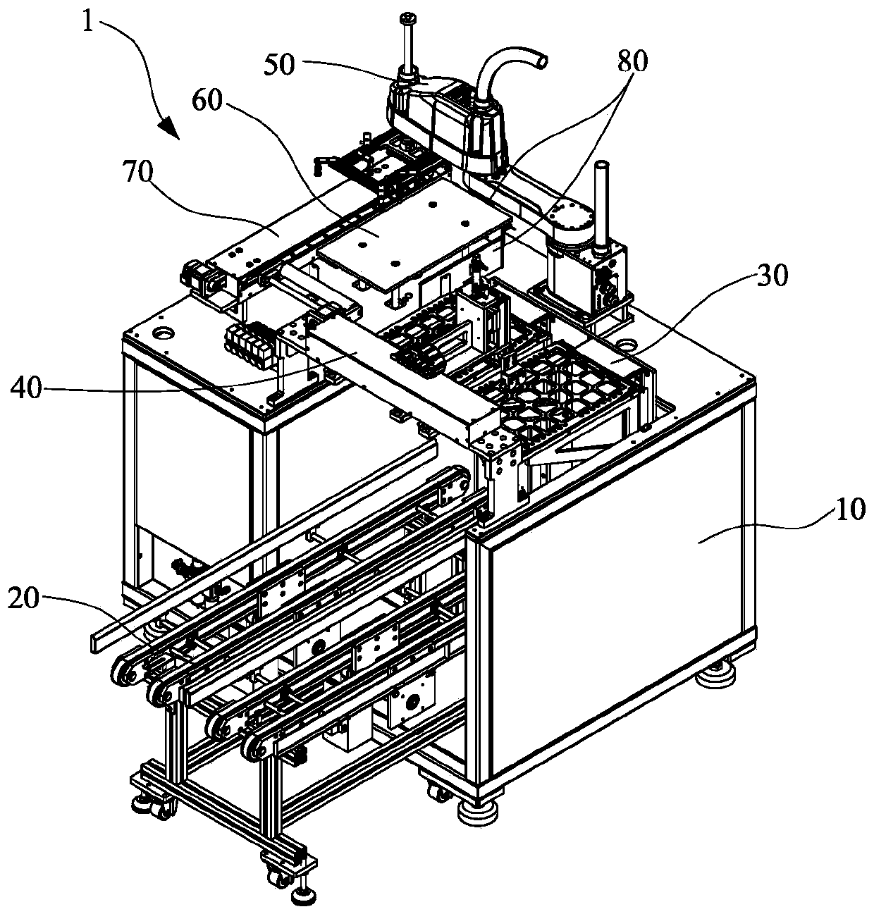
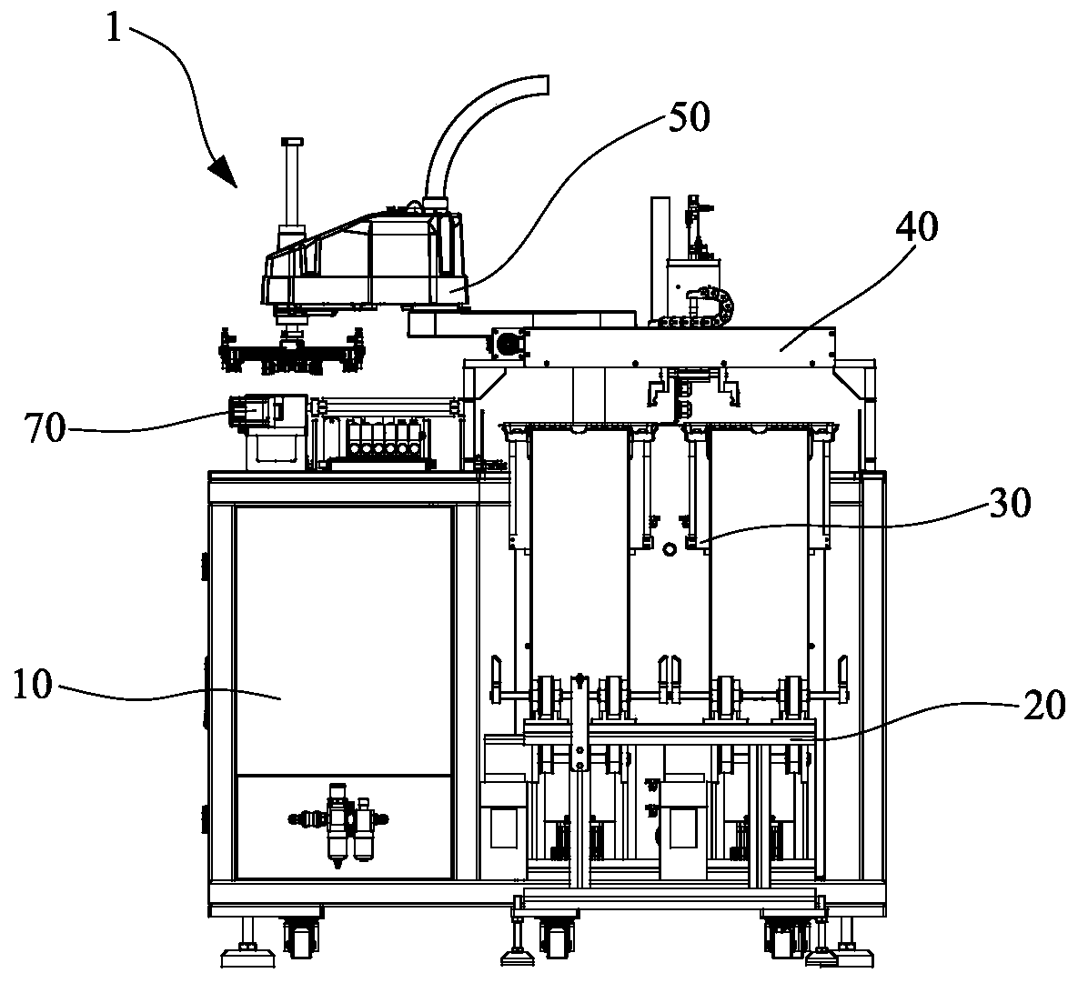

Image

  • Silk-screen feeding and discharging device
  • Silk-screen feeding and discharging device
  • Silk-screen feeding and discharging device

Examples


Embodiment Construction

[0055] In order to further explain the technical solution of the present invention, the present invention will be described in detail below through specific examples.

[0056] In describing the present invention, it should be understood that the terms "center", "longitudinal", "transverse", "upper", "lower", "front", "rear", "left", "right", " Vertical", "horizontal", "top", "bottom", "inner", "outer" and other indication orientations or positional relationships are based on the orientations or positional relationships shown in the drawings, and are only for the convenience of describing the present invention and simplifying Describes, but does not indicate or imply that the device or element referred to must have a specific orientation, be constructed in a specific orientation, and operate in a specific orientation, and therefore should not be construed as limiting the invention. In the description of the present invention, unless otherwise specified, "plurality" means two or...


PUM


Abstract

The invention discloses a silk-screen feeding and discharging device. The silk-screen feeding and discharging device comprises a rack, a tray conveying and buffering mechanism, a tray feeding and discharging mechanism, a tray carrying mechanism, a material moving manipulator and a feeding platform mechanism, wherein a workbench and a tray feeding and discharging space are arranged on the rack; thetray conveying and buffering mechanism penetrates through the tray feeding and discharging space of the rack; the tray feeding and discharging mechanism can move up and down relative to the tray conveying and buffering mechanism; the tray carrying mechanism is transversely erected on the portion, above the corresponding tray conveying and buffering mechanism, of the rack and moves in the space above the tray feeding and discharging mechanism; the material moving manipulator is arranged on the portion, on one side of the tray feeding and discharging mechanism, of the rack and rotates and movesin the space above the rack at multiple stations; and the feeding platform mechanism is arranged on the workbench of the rack and is close to the side, close to the tray feeding and discharging mechanism, of the material moving manipulator. The silk-screen feeding and discharging device can be matched with an existing semi-automatic silk-screen printing machine and transformed into a full-automatic silk-screen printing machine, existing equipment resources are fully utilized, and automation of silk-screen printing of products is achieved.

Description

technical field [0001] The invention relates to the technical field of production equipment for flexible circuit boards, in particular to a screen printing loading and unloading equipment. Background technique [0002] In the production process of flexible circuit boards, silk screen printing technology is often required to print character ink, resist ink, etc. for flexible circuit board products. Due to the thin and soft characteristics of flexible circuit boards, the current operation method mainly relies on manual operation of semi-automatic screen printing machines. It is completed by one machine, and one person operates one screen printing machine, which takes a lot of manpower. Although there are some fully automatic screen printing machines on the market, they are expensive, and most factories have purchased multiple semi-automatic screen printing machines in the early stage. If new automatic screen printing equipment is introduced, the existing semi-automatic screen ...

Claims


Application Information

Patent Timeline
IPC IPC(8): B65G37/02B65G43/08B65G47/91B65G47/90B65G59/04B65G59/02B65G57/03B41F23/00
CPCB41F23/002B65G37/02B65G43/08B65G47/901B65G47/912B65G57/035B65G59/026B65G59/045B65G2201/0258B65G2203/041B65G2203/042
Inventor 赵继伟包克兵续振林陈明峰朱石宝
Owner XIAMEN HONGXIN ELECTRON TECH
Learn More