A Microjet Method for Controlling Flow Separation of Suction Surface of Compressor/Fan Stator Blades

A fan stator and flow separation technology, applied in the direction of machines/engines, blade support components, pump control, etc., can solve problems such as weak flow control on the suction surface

Active Publication Date: 2021-04-20
NANJING UNIV OF AERONAUTICS & ASTRONAUTICS
View PDF8 Cites 0 Cited by
  • Summary
  • Abstract
  • Description
  • Claims
  • Application Information

AI Technical Summary

Problems solved by technology

Since the energy difference between the pressure surface and the suction surface is small, the jet formed by the groove has weak control over the flow of the suction surface

Method used


Image

  • A Microjet Method for Controlling Flow Separation of Suction Surface of Compressor/Fan Stator Blades
  • A Microjet Method for Controlling Flow Separation of Suction Surface of Compressor/Fan Stator Blades

Examples


Embodiment

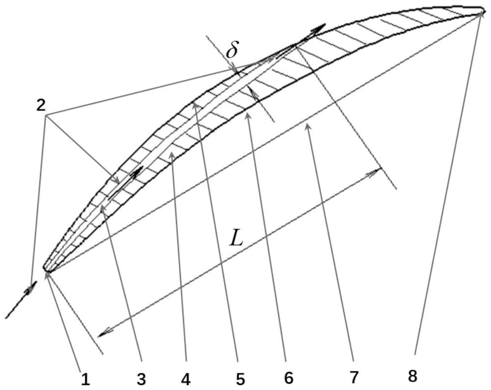
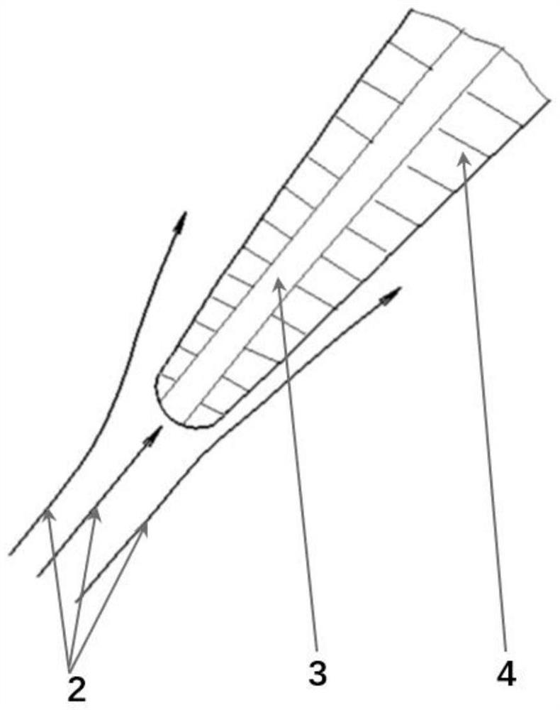
[0016] following by figure 1 The implementation method of the present invention using velocity impulse to form micro-jet control compressor stator suction surface boundary layer is illustrated.

[0017] Axial flow compressor / fan stator blades are formed by stacking several airfoils along the radial direction according to a certain stacking rule, using the airfoil as the skeleton and covering the skeleton with a spline surface. Therefore, the airfoil is the basic element of the blade, and the aerodynamic performance of the blade depends on the airfoil. The present invention is characterized in that: the compressor / fan stator blades are hollow, and the hollow blades are composed of slotted blade profiles, that is, blade profiles (4). One end of the airfoil slit (3) opened on the airfoil (4) is located at the leading edge (1) of the airfoil; the other end is located at the position where the airfoil suction surface (5) needs to be blown off of the boundary layer. When the airfl...


PUM


Abstract

The invention discloses a micro-jet method for controlling the flow separation of the suction surface of a compressor / fan stator blade. The technical feature of the invention is that a slit is opened inside the airfoil to form a slit airfoil, and one end of the airfoil slit is It is located at the leading edge of the airfoil, and the other end is located on the suction surface of the airfoil; when the airflow passes through the blade, a small amount of airflow flows into the gap of the airfoil and is ejected from the outlet of the suction surface of the airfoil. The method proposed by this invention to form a micro-jet to control the boundary layer on the suction surface of the blade by using the velocity impulse can be used in a class of axial flow compression machines such as compressors and fans to reduce flow loss and improve efficiency.

Description

technical field [0001] The invention belongs to the technical field of aerodynamics, and in particular relates to a micro-jet method for controlling the flow separation of the suction surface of a compressor / fan stator blade, which aims to form a micro-jet flow by using velocity impulse to control the flow separation of the compressor / fan stator suction surface. Background technique [0002] The axial flow compressor / fan stator cooperates with the rotor to form the compressor / fan stage, and the stator is used to change the airflow direction and decelerate and boost. The higher the compressor / fan stage pressure ratio, the higher the inlet speed of the stator, the larger the airflow angle, the thicker the boundary layer on the suction surface of the blade, and even the flow separation, and the greater the flow loss. In order to improve the thrust-to-weight ratio of aero-engines, aviation compressors / fans have always been developing towards higher pressure ratios. Therefore, f...

Claims


Application Information

Patent Timeline
Patent Type & Authority Patents(China)
IPC IPC(8): F04D29/38F04D29/44
CPCF04D29/388F04D29/441F01D5/145F05D2220/36F05D2220/3216F05D2260/81F04D29/324F04D29/682F04D29/684F01D5/18F01D9/02F04D27/005F04D29/384F05D2240/12F04D29/544F04D29/681
Inventor 周正贵郑欢叶新龙
Owner NANJING UNIV OF AERONAUTICS & ASTRONAUTICS
Why Eureka
Try Eureka