Fire cover for gas cooker

A gas stove and fire cover technology, applied in the direction of burner, combustion method, combustion type, etc., can solve the problems affecting the fire transmission performance, the deformation of the fire cover body, the blockage of the fire transmission groove, etc., so as to ensure the fire transmission performance and applicability The effect of enhancing and securing gas concentration

Pending Publication Date: 2020-06-09
NINGBO FOTILE KITCHEN WARE CO LTD
View PDF1 Cites 0 Cited by
  • Summary
  • Abstract
  • Description
  • Claims
  • Application Information

AI Technical Summary

Problems solved by technology

[0002] At present, most of the traditional burner fire caps sold on the market are milled with one groove, that is, a fire pilot groove is milled on the top of the fire cap body. Disconnected, so it is easy to cause deformation of the fire cover body, thus affecting the ignition effect
For example, the Chinese invention patent "Gas burner with fire transmission device and flameout protection function" whose patent number is 201220464214.0 (notification number is CN202813375U) discloses a similar fire transmission structure. ring fire spray hole, and the outer ring fire transmission device is also provided on the fire spray right of the outer ring. The outer ring fire transmission hole and the outer ring fire transmission groove on the platform and the outer ring fire spraying ring are composed of the outer ring fire transmission hole and the outer ring fire transmission groove, and the outer ring fire transmission hole and the outer ring fire transmission groove are connected with a The flame-spray holes of the outer ring are connected to realize rapid fire transmission; the fire-transfer channel of this fire-transfer structure is open, and the fire transmission is linear, that is, the fire-transfer channel is exposed on the surface of the outer ring fire cover. This design has a The advantage is that the supply of secondary air in the fire transfer tank is sufficient, and the open fire transfer tank can ensure the supply of secondary air when the flame burns in the fire transfer tank, which is conducive to flame combustion and fire transmission, and has the characteristics of fast fire transmission. However, the open fire transmission tank has two disadvantages. 1. It is easy to cause the fire transmission tank to be blocked, that is, the soup flowing down from the bottom of the pot is easy to flow into the fire transmission tank, and the blockage will affect the fire transmission performance. The main reason for the blockage and maintenance of the fire transmission channel; 2. The open fire transmission channel has high requirements on the damper of the cooker, because after the damper is opened, the air volume will be too large at one time, which will cause the air velocity to be too high, so that the gas at the ignition port of the fire transmission channel will be blown Dilution will cause flame separation or fire loss during combustion. Therefore, the structural feature of the open fire transfer tank is poor flame stability. Therefore, to ensure the fire transfer performance of the open fire transfer tank, the damper is basically closed very small. , but closing the damper is not conducive to the combustion efficiency of the stove, and it is also not conducive to the emission of smoke, which greatly affects the performance of the stove; and another hidden fire channel will easily fail to achieve stability due to the lack of oxygen inside the fire channel. The burning of the burner, and the phenomenon of continuous tempering and detonation, will cause the user a sense of fear. For this reason, it is necessary to further improve the fire transmission groove of the burner fire cover

Method used


Image

  • Fire cover for gas cooker
  • Fire cover for gas cooker
  • Fire cover for gas cooker

Examples


Embodiment Construction

[0020] The present invention will be further described in detail below in conjunction with the accompanying drawings and embodiments.

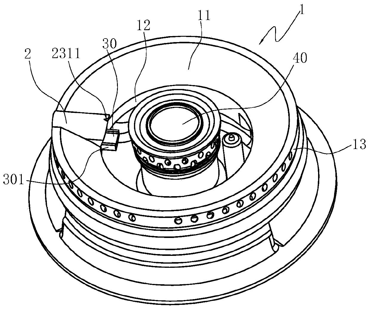
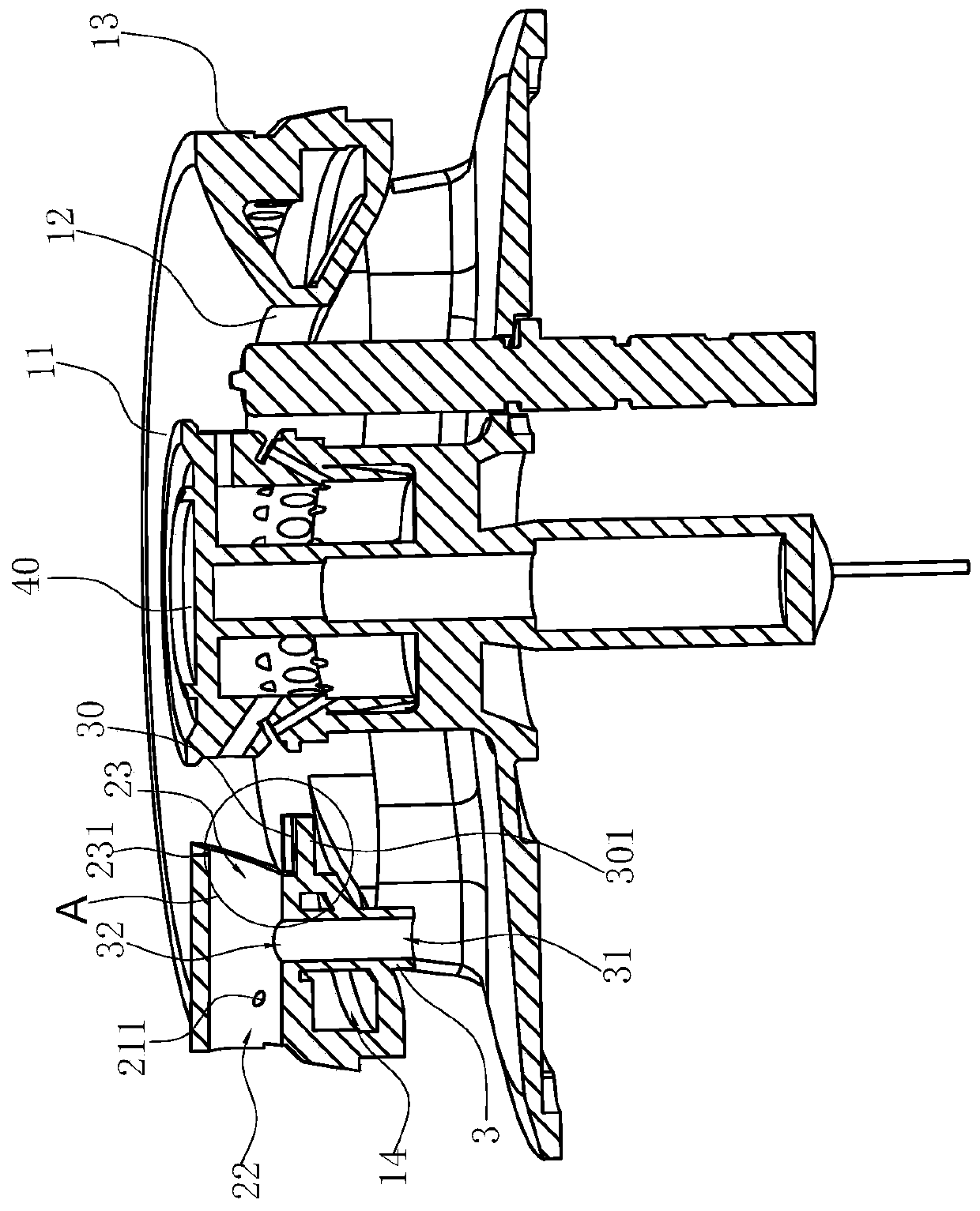
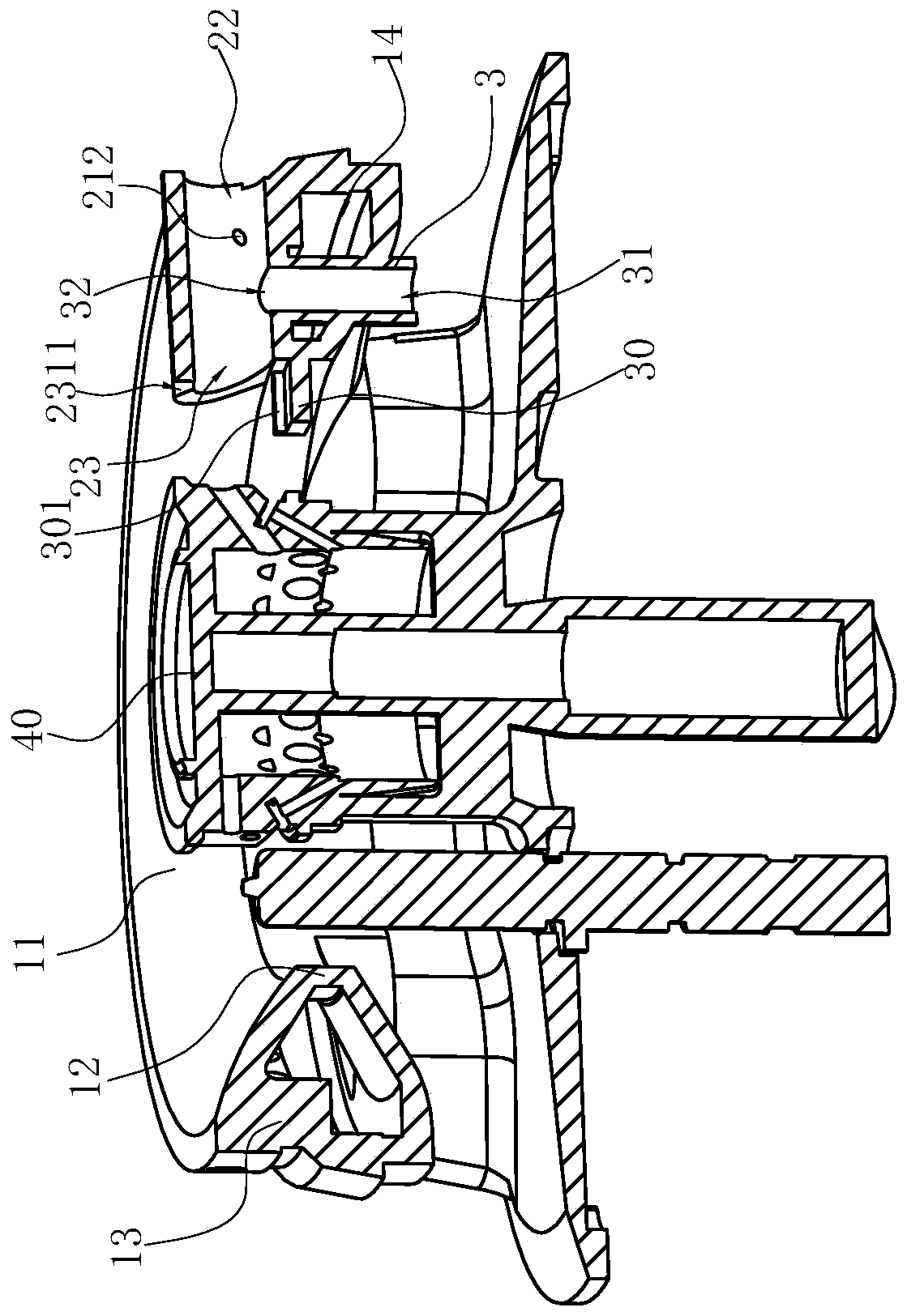
[0021] Such as Figure 1~4 Shown is the preferred embodiment of the present invention. The fire cover used for the gas stove in this embodiment includes a fire cover body 1, and the annular top wall 11 of the fire cover body 1 extends vertically or obliquely downward from the inner edge and the outer edge of the annular top wall 11. A gas mixing chamber 14 is formed between the inner ring wall 12 and the outer ring wall 13 of the fire cover body 1. The ring-shaped top wall 11 of the fire cover body 1 is radially provided with a fire passage, and the fire passage is provided with an air inlet connected to the gas mixture chamber 14. Holes, air intake holes can be set at the bottom of the fire passage, the outer opening 22 of the fire passage is located at the outer ring wall 13, the inner opening 23 of the fire passage is towards the center of...


PUM


Abstract

The invention relates to a fire cover for a gas cooker. The fire cover comprises a fire cover body. A gas mixing cavity is formed among the annular top wall of the fire cover body, an inner ring walland an outer ring wall, wherein the inner ring wall and the outer ring wall stretch vertically or obliquely and downwards from the inner side edge and outer side edge of the annular top wall. A fire introducing channel is radially disposed on the annular top wall of the fire cover body and is provided with a gas inlet hole communicating with the gas mixing cavity. The fire cover is characterized in that a fire introducing table with a U-shaped cross section stretches towards the center of the fire cover body and is formed on the inner ring wall and below an inner side opening of the fire introducing channel. Compared with the prior art, the fire cover have the advantages that because of sufficient air, fuel gas in the fire introducing table reaches a fuel gas explosion range easily, an explosion-like effect is formed after ignition, and the fire passing speed is high. Meanwhile, a convex edge of the fire introducing table can effectively prevent the fuel gas of the fire introducing channel from being diluted by external cold air, and the gas concentration of the fire introducing table is ensured.

Description

technical field [0001] The invention relates to a burner for a gas stove, in particular to a fire cover for a gas stove. Background technique [0002] At present, most of the traditional burner fire caps sold on the market are milled with one groove, that is, a fire pilot groove is milled on the top of the fire cap body. If disconnected, it is easy to cause deformation of the fire cover body, thereby affecting the ignition effect. For example, the Chinese invention patent "Gas burner with fire transmission device and flameout protection function" whose patent number is 201220464214.0 (notification number is CN202813375U) discloses a similar fire transmission structure. ring fire spray hole, and the outer ring fire transmission device is also provided on the fire spray right of the outer ring. The outer ring fire transmission hole and the outer ring fire transmission groove on the platform and the outer ring fire spraying ring are composed of the outer ring fire transmissio...

Claims


Application Information

Patent Timeline
IPC IPC(8): F23D14/04F23D14/46F23D14/58F23D14/64
CPCF23D14/04F23D14/46F23D14/58F23D14/64
Inventor 刘晓刚王帅东柯情徐强郑军妹
Owner NINGBO FOTILE KITCHEN WARE CO LTD
Why Eureka
Try Eureka