Burner fire cover for gas cooking appliance

A gas cooker and burner technology, which is applied to gas fuel burners, burners, combustion methods, etc., can solve problems such as insufficient combustion and reduced air volume, and achieve the effects of enhanced applicability, reduced flow rate, and good flame stabilization Effect

Pending Publication Date: 2019-08-06
NINGBO FOTILE KITCHEN WARE CO LTD
View PDF1 Cites 3 Cited by
  • Summary
  • Abstract
  • Description
  • Claims
  • Application Information

AI Technical Summary

Problems solved by technology

[0005] Since the horizontal fire hole is hidden in the fire cover body, the anti-blocking performance of the fire hole can be improved, but at the same time, the problem of insufficient combustion caused by the reduction of the air volume of the horizontal fire hole must be solved. Corresponding to the lower part of the inner opening of the transverse fire hole is formed with a gap

Method used


Image

  • Burner fire cover for gas cooking appliance
  • Burner fire cover for gas cooking appliance
  • Burner fire cover for gas cooking appliance

Examples


Embodiment 1

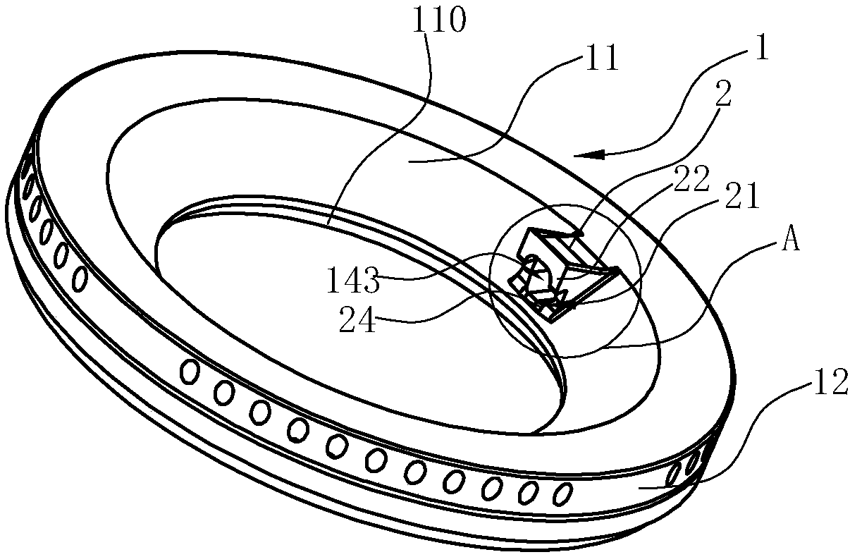
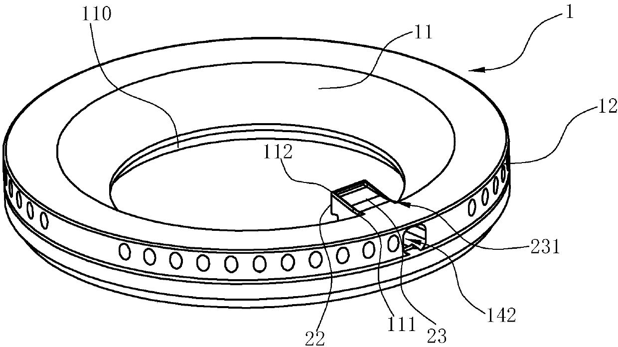
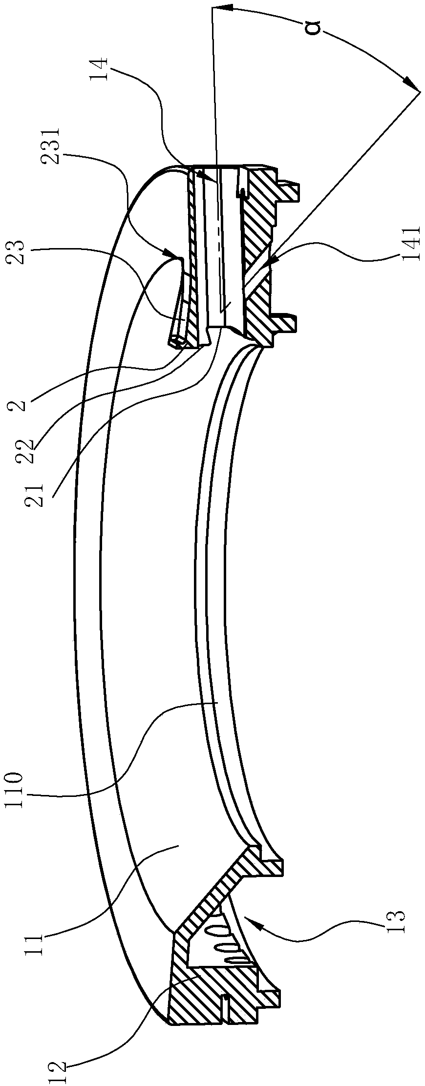
[0025] Such as Figure 1~4 Shown is the preferred embodiment of the present invention. The burner fire cover of the gas cooker in this embodiment includes a fire cover body 1, an annular top wall of the fire cover body 1 and vertical or obliquely extending downwards from the inner edge 110 and the outer edge of the annular top wall. A gas mixing chamber 13 is formed between the inner ring wall 11 and the outer ring wall 12, and a horizontal fire hole 14 is opened in the radial direction inside the fire cover body 1, and a passage connecting the gas mixing chamber 13 is opened at the bottom of the horizontal fire hole 14. The hole 141, the lateral opening 142 of the lateral fire opening 14 is on the outer ring wall 12, the inner opening 143 of the horizontal fire opening 14 is on the inner ring wall 11, and the inner ring wall 11 is facing the fire cover body 1 on the inner wall corresponding to the opening 143 on the inner side of the horizontal fire opening 14 A boss 2 is fo...

Embodiment 2

[0031] The structure is basically the same as that of Embodiment 1, the difference is that there is no notch 21 at the lower part of the opening 143 inside the corresponding horizontal fire hole 14 on the vertical end face of the horizontal fire hole 14, as Figure 5 shown.

Embodiment 3

[0033] The structure is basically the same as that of Example 1, the difference is that a strip-shaped groove 20 corresponding to the horizontal fire-fire hole 14 is provided below the horizontal fire-fire hole 14, and the strip-shaped groove 20 can further reduce the gas outlet speed and improve the flame stabilization ability ,Such as Figure 6 shown.


PUM


Abstract

The invention relates to a burner fire cover for a gas cooking appliance. The burner fire cover includes a fire cover body; an air mixing chamber is formed between an annular top wall, an inner ring wall and an outer ring wall of the fire cover body, a transverse fire leading hole is disposed in the radial direction inside the fire cover body, and a through hole communicating with the air mixing chamber is disposed at the bottom of the transverse fire leading hole; and the burner fire cover is characterized in that: an outer side opening of the transverse fire leading hole is disposed in the outer ring wall; an inner side opening of the transverse fire leading hole is disposed in the inner ring wall; the inner ring wall extends radially toward a center of the fire cover body at a peripheral wall corresponding to the inner side opening of the transverse fire leading hole to form a boss; and an included angle at which the center line projects onto a plane at the top of the boss is an acute angle, and an included angle [alpha] between the center line of the through hole and the center line of the transverse fire leading hole is the acute angle. Compared with the prior art, the burnerfire cover is advantageous in that: fuel gas, primary air and secondary air are mixed into a mixed gas and then can be directly collided with the top of the boss, the mixing uniformity of the fuel gasand the air in the mixed gas is improved, the flow rate is also reduced, the flame stablizing performance is improved, and a good flame stablizing effect is produced on a flame at the transverse fireleading hole.

Description

technical field [0001] The invention relates to a burner for a gas cooker, in particular to a burner fire cover for a gas cooker. Background technique [0002] At present, most of the traditional burner fire caps sold on the market are milled with one groove, that is, a fire pilot groove is milled on the top of the fire cap body. If disconnected, it is easy to cause deformation of the fire cover body, thereby affecting the ignition effect. For example, the Chinese invention patent "Gas burner with fire transmission device and flameout protection function" whose patent number is 201220464214.0 (notification number is CN202813375U) discloses a similar fire transmission structure. ring fire hole, and the outer ring fire transmission device is also provided on the outer ring fire spray right, the outer ring fire transmission device is a boss installed on the inner wall of the outer ring fire spray ring The outer ring fire transmission hole and the outer ring fire transmission ...

Claims


Application Information

Patent Timeline
IPC IPC(8): F23D14/46F23D14/62
CPCF23D14/46F23D14/62
Inventor 戎胡斌邵海忠吴丽波王帅东郑军妹
Owner NINGBO FOTILE KITCHEN WARE CO LTD
Why Eureka
Try Eureka