
An automatic integration device for power cords before injection molding that combines correction and shaping

A technology for integrating devices and power cords, which is applied in the direction of circuits, electrical components, circuit/collector components, etc., can solve problems such as low production efficiency, correcting to a specified state, and increasing production costs, so as to improve the quality of correction and position accuracy , The effect of facilitating injection molding

Active Publication Date: 2021-04-13
浙江海宁普赛自动化科技有限公司
View PDF9 Cites 0 Cited by
  • Summary
  • Abstract
  • Description
  • Claims
  • Application Information

AI Technical Summary

Problems solved by technology

[0006] The traditional manual feeding method will not only make the correction quality of the power cord easily affected by artificial factors, but also make it difficult for the correction station to correct the power cord pins to the specified state when the feeding position is unqualified
Moreover, manual feeding requires a lot of manpower, equipment and space. Compared with mechanical automatic feeding, the production efficiency is low and the production cost is increased.

Method used


Image

  • An automatic integration device for power cords before injection molding that combines correction and shaping
  • An automatic integration device for power cords before injection molding that combines correction and shaping
  • An automatic integration device for power cords before injection molding that combines correction and shaping

Examples


Embodiment Construction

[0029] The specific implementation manners of the present invention will be further described in detail below in conjunction with the accompanying drawings and embodiments. The following examples are used to illustrate the present invention, but are not intended to limit the scope of the present invention.

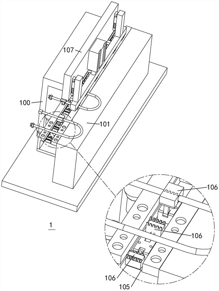
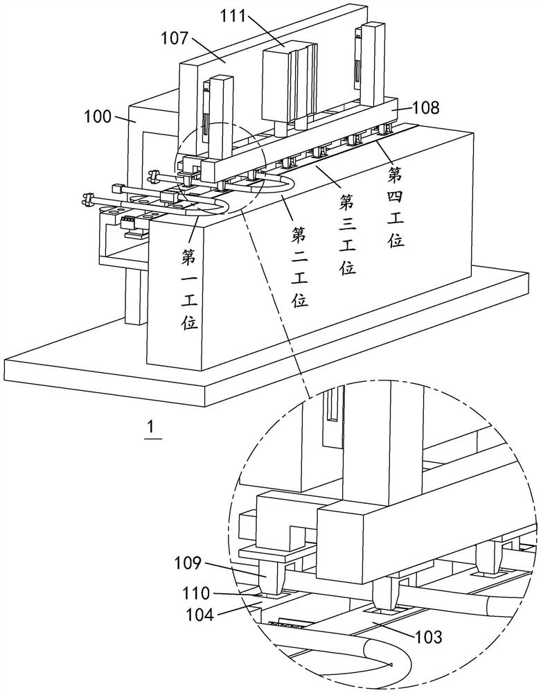
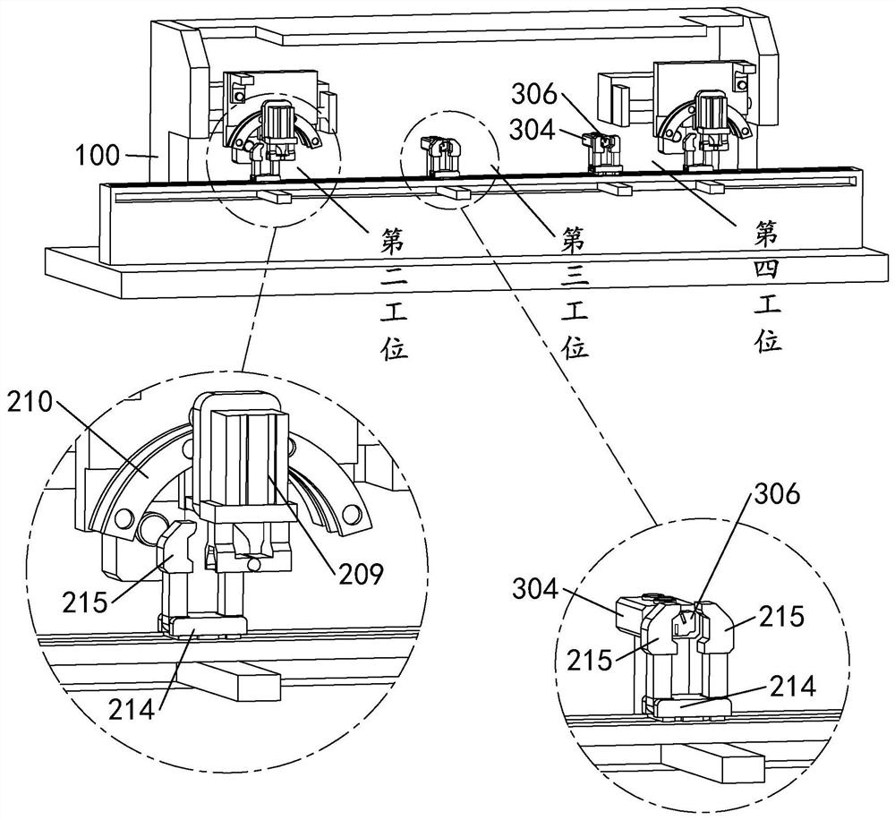
[0030] The following reference Figure 1 to Figure 9 The present invention will be described.

[0031]An automatic integration device for power cords before injection molding that combines correction and shaping, including an equipment bracket 100, a power cord placement table 101, a clamping mechanism and a drive mechanism, the power cord placement table 101 is arranged on the front side of the equipment bracket 100 and the lower end is fixed on the On the ground, the rear side of the power cord placing table 101 is provided with a supporting table 1 103 and a supporting table 2 104 . The heights are the same, and the power pin wires are placed in a U shape on the suppo...


PUM


Abstract

The invention discloses an automatic integration device for power cords before injection molding that combines correction and shaping, including a circular conveying mechanism and a straightening mechanism in the straightening area, a twisting mechanism located in the shaping area, and a transfer device between the straightening area and the shaping area mechanism, the circular conveying mechanism includes equipment support, a power cord placement table for cables, a clamping mechanism for clamping cables, and a driving mechanism for driving the clamping mechanism to move with cables; the rectification The mechanism includes a cable socket correction mechanism and a cable pin correction mechanism; the transfer mechanism includes a clamping mechanism, a transmission mechanism, and a stabilizing mechanism for supporting the cable socket after correction; the twisted wire The mechanism includes an insert fixing block for supporting the cable pin part and a rotary drive mechanism for driving the insert fixing block to drive the cable pin part to rotate. The degree of automation is high, and the processing accuracy and work efficiency are improved.

Description

technical field [0001] The invention relates to the technical field of power cord production, in particular to an automatic integration device for power cords before injection molding that combines correction and shaping. Background technique [0002] The power pin refers to the device that connects electrical appliances and other devices to the power supply. The existing power pins usually use injection molding to press the pins and wires together through high temperature and high pressure. Once formed, they cannot be assembled and disassembled. The power pin has the advantages of stability and safety. [0003] During the automatic production process of the power pin cord, it is necessary to correct the angle of the pin part and the plug part of the power cord first (see the attached manual Figure 9 , the upper part in the figure is the plug part, and the lower part is the pin part), and then the pin part is twisted to make the three wires there close, and then transported...

Claims


Application Information

Patent Timeline
Patent Type & Authority Patents(China)
IPC IPC(8): H01R43/048H01R43/052H01R43/18H01R43/28
CPCH01R43/048H01R43/052H01R43/18H01R43/28
Inventor 余崇威潘克飞
Owner 浙江海宁普赛自动化科技有限公司
Learn More