
Vacuum reaction tank

A reaction tank and vacuum technology, applied in gas treatment, membrane technology, evaporation, etc., can solve the problems of low evaporation efficiency and inability to denitrify, and achieve the effect of improving sliding effect, avoiding tilting and bending, and enhancing mixing degree.

Pending Publication Date: 2020-06-12
孙安杰
View PDF3 Cites 0 Cited by
  • Summary
  • Abstract
  • Description
  • Claims
  • Application Information

AI Technical Summary

Problems solved by technology

The invention is mainly used to solve the problem that the existing vacuum reaction tank needs an external heating source, the evaporation efficiency is not high, and at the same time, it cannot be combined with flue gas for denitrification at the first time

Method used


Image

  • Vacuum reaction tank
  • Vacuum reaction tank
  • Vacuum reaction tank

Examples


Embodiment Construction

[0025] use Figure 1-Figure 5 A vacuum reaction tank according to one embodiment of the present invention will be described as follows.

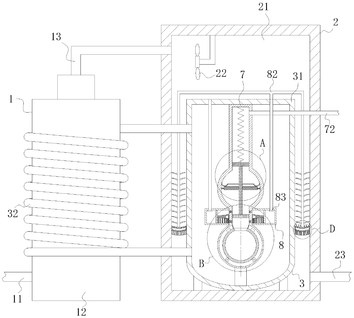
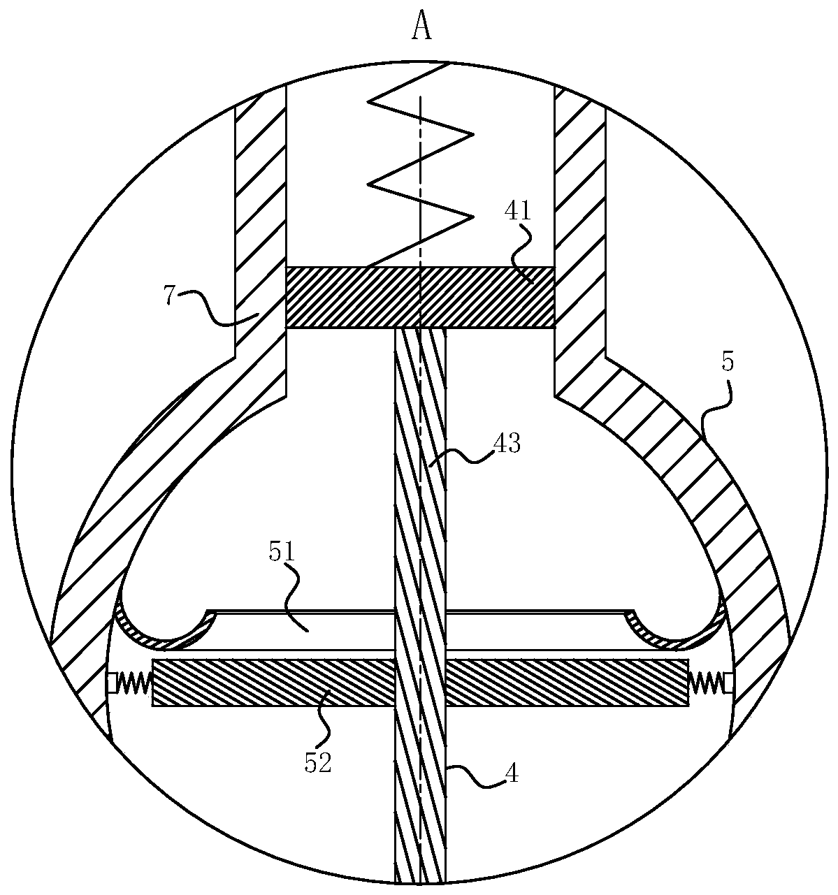
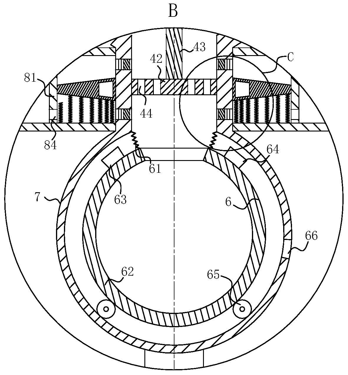
[0026] Such as Figure 1-Figure 5 As shown, a vacuum reaction tank according to the present invention includes a smoke mechanism 1, a reaction mechanism 2, a heating mechanism 3, an intermittent cycle mechanism 4, a first evaporation mechanism 5 and a second evaporation mechanism 6; the smoke mechanism 1 includes an air inlet pipe 11, a smoke chamber 12 and a first air outlet pipe 13; the air inlet pipe 11 is fixedly connected to the lower wall of the left end of the smoke chamber 12; the left end of the first air outlet pipe 13 is fixedly connected to the smoke chamber In the upper end wall of 12, the right end of the first air outlet pipe 13 is fixedly interspersed with a reaction mechanism 2; the reaction mechanism 2 includes a reaction chamber 21, fan blades 22 and a second air outlet pipe 23; the reaction chamber 21 is located in the s...


PUM


Abstract

The invention belongs to the technical field of liquid ammonia evaporation devices, and particularly relates to a vacuum reaction tank. The vacuum reaction tank comprises a flue gas mechanism, a reaction mechanism, a heating mechanism, an intermittent circulating mechanism, a first evaporation mechanism and a second evaporation mechanism; the lower end of a heating cavity is fixedly installed on the lower surface in a reaction chamber, a heating pipe is fixedly connected into the left end wall of the heating cavity in a penetrating mode, and a special-shaped pipe is fixedly connected to the upper surface in the heating cavity; the left end of the heating pipe is connected to the outer surface of a flue gas cavity in a winding manner; a first air hole is formed in the lower side wall of thespecial-shaped pipe, and a liquid inlet pipe is fixedly connected into the right wall of the upper end of the special-shaped pipe; and a hydrophobic membrane and a first one-way valve are fixedly connected into the first air hole, and a connecting ring is arranged on the outer side of the first air hole. The problems that an existing vacuum reaction tank needs to be externally connected with a heating source, evaporation efficiency is not high, and meanwhile the existing vacuum reaction tank cannot be combined with flue gas for denitration at the first time are mainly solved.

Description

technical field [0001] The invention belongs to the technical field of liquid ammonia evaporation devices, in particular to a vacuum reaction tank. Background technique [0002] Flue gas denitrification refers to the reduction of generated NOX to N2, thereby removing NOX in flue gas. According to the treatment process, it can be divided into wet denitrification and dry denitrification. Some researchers at home and abroad have also developed a method of using microorganisms to treat NOX exhaust gas. Since more than 90% of NOx in the flue gas discharged from the combustion system is NO, and NO is difficult to dissolve in water, the wet treatment of NOx cannot Use simple washing method. The principle of flue gas denitrification is to use oxidant to oxidize NO into NO2, and then absorb the generated NO2 with water or alkaline solution to achieve denitrification. For flue gas denitrification in thermal power plants, ammonia is mainly used as a reducing agent to convert nitrogen ...

Claims


Application Information

Patent Timeline
Patent Type & Authority Applications(China)
IPC IPC(8): B01D53/56B01D53/76B01D1/00
CPCB01D1/00B01D53/56B01D53/76B01D2251/2062B01D2258/0283
Inventor 孙安杰王和平郑智
Owner 孙安杰
Learn More