
Turning combined machine tool with retractable tool

A combined machine tool and cutting tool technology, which is applied in the direction of manufacturing tools, metal processing machinery parts, clamping, etc., can solve the problems that affect the processing efficiency, the length of the turning tool cannot be adjusted, and the efficiency is low, so as to improve the turning positioning accuracy and surface turning accuracy , improve turning efficiency and tool life, and avoid major losses

Pending Publication Date: 2020-06-12
盐城威佳机床制造有限公司
View PDF7 Cites 1 Cited by
  • Summary
  • Abstract
  • Description
  • Claims
  • Application Information

AI Technical Summary

Problems solved by technology

[0003] The current drill-turn combination machine tool realizes turning processing by installing a turning tool on the tool holder of the machine tool. Usually, the tool is fixedly installed on the turning tool holder, and the length of the turning tool cannot be adjusted. When turning the outer hole, it is impossible to achieve high-speed rotation, depth-controllable turning, and transverse through-drilling of the workpiece. Since the tool length of the machine tool cannot be flexibly adjusted, it is necessary to stop the machine to replace the tool. The tool change process is complicated and the efficiency is low, which affects the processing efficiency. The problem

Method used


Image

  • Turning combined machine tool with retractable tool
  • Turning combined machine tool with retractable tool
  • Turning combined machine tool with retractable tool

Examples


Embodiment 1

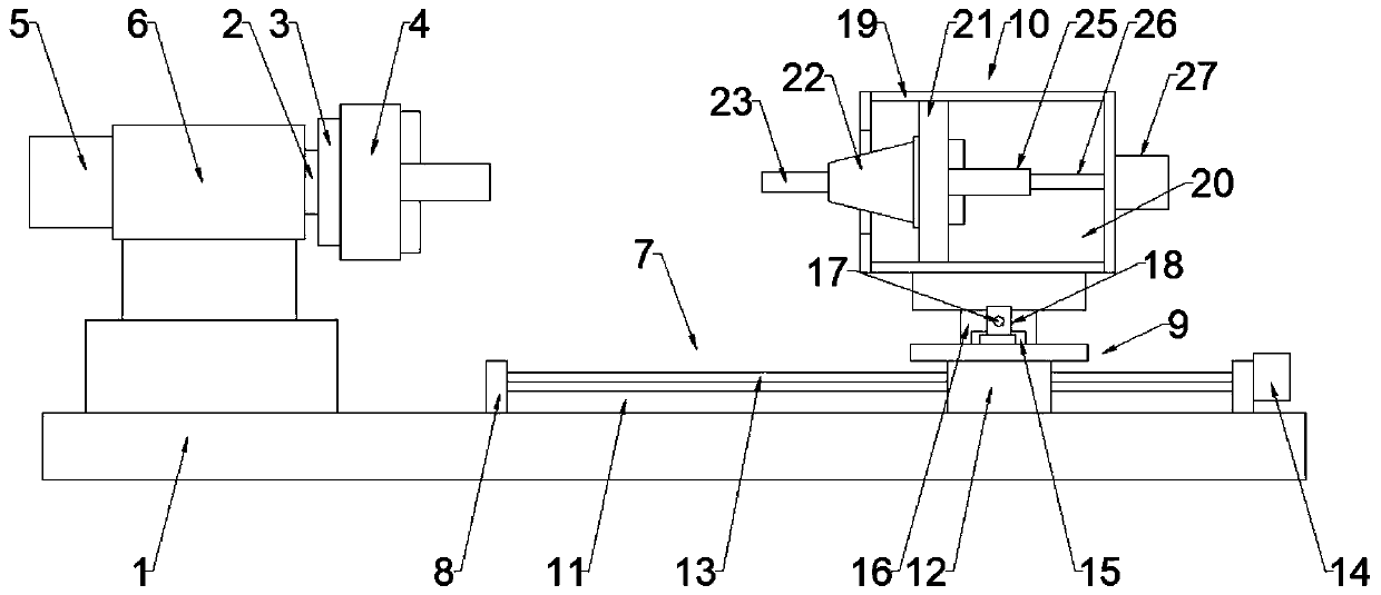
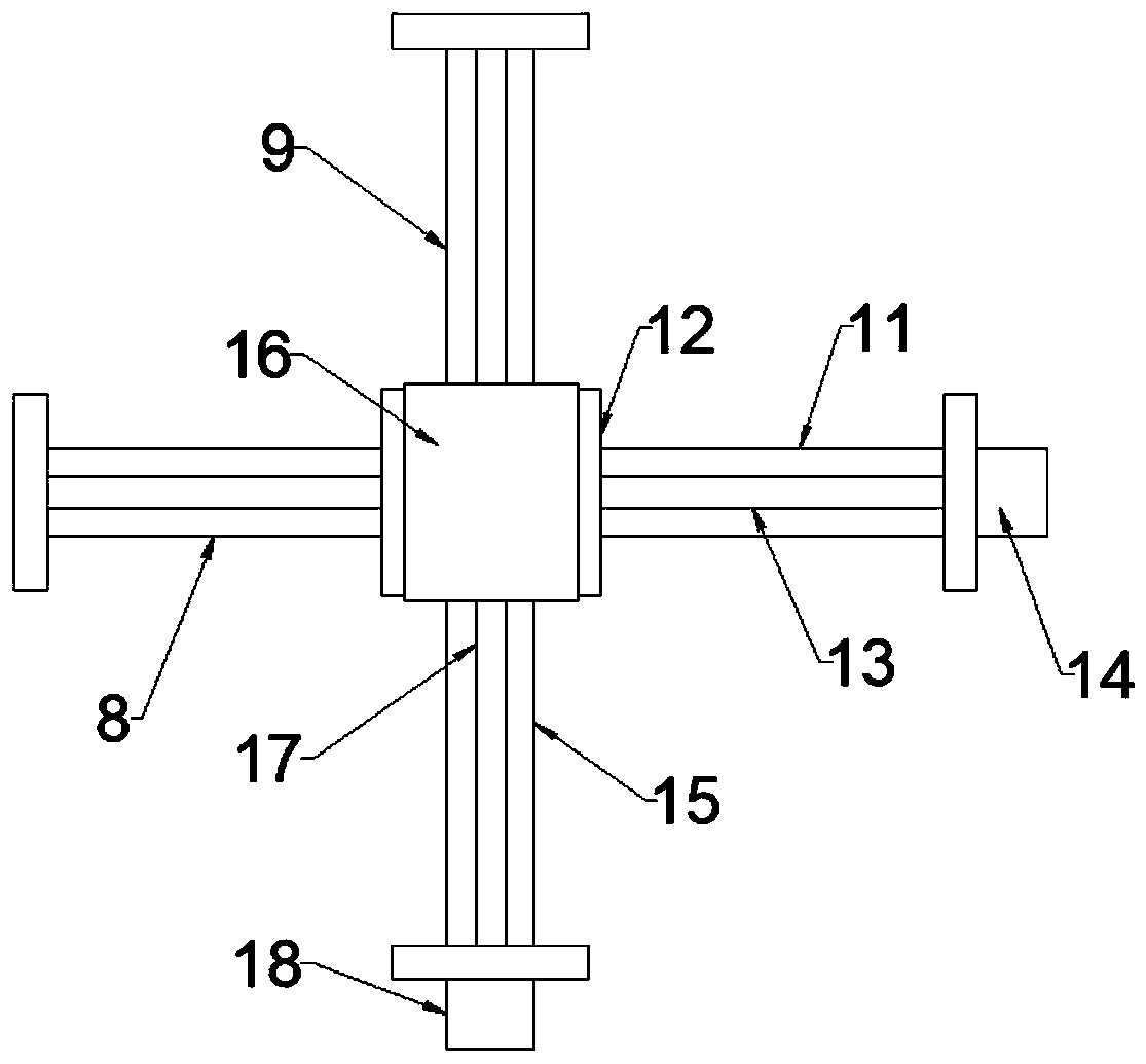
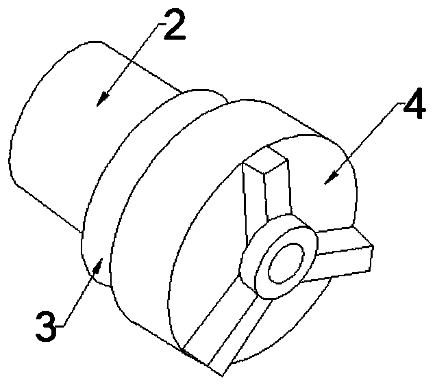
[0027] see Figure 1 to Figure 5 As shown, a turning combination machine tool with shrinkable cutting tools includes a machine bed 1, a workpiece fixture 4 and a CNC tool holder 7, the workpiece fixture 4 is installed on a rotating disk 3, and the rotating disk 3 is fixed on one end of the machine tool spindle 2, The machine tool spindle 2 is rotatably erected in the fixed seat 6 on the machine bed 1, the other end of the machine tool spindle 2 is connected to the first motor 5, and the first motor 5 is installed on the fixed seat 6, and the workpiece is fixed on the workpiece fixture 4 during processing. When working, the first motor 5 starts and drives the machine tool spindle 2, the rotating disk 3 and the workpiece fixture 4 to rotate, thereby driving the workpiece to rotate at high speed.

[0028] The CNC tool rest 7 is installed on the machine bed 1, and the CNC tool rest 7 includes a transverse guide rail assembly 8, a longitudinal guide rail assembly 9 and a tool assem...

Embodiment 2

[0034] see Figure 1 ~ Figure 3 As shown, a turning combination machine tool with shrinkable cutting tools includes a machine bed 1, a workpiece fixture 4 and a CNC tool holder 7, the workpiece fixture 4 is installed on a rotating disk 3, and the rotating disk 3 is fixed on one end of the machine tool spindle 2, The machine tool spindle 2 is rotatably installed in the fixed seat 6 on the machine bed 1, the other end of the machine tool spindle 2 is connected to the first motor 5, and the first motor 5 is installed on the fixed seat 6;

[0035] The CNC tool rest 7 is installed on the machine bed 1, and the CNC tool rest 7 includes a transverse rail assembly 8, a longitudinal rail assembly 9 and a cutter assembly 10; the cutter assembly 10 includes a cutter head housing 19, a tool holder 22 and a cutter Body 23, wherein the cutter head housing 19 is fixed on the longitudinal slider 16 of the longitudinal guide rail assembly 9, the cutter head housing 19 is provided with a contra...


PUM


Abstract

The invention discloses a turning combined machine tool with a retractable tool, belongs to the technical field of numerical control machines, and solves the problems that the length of a tool of an existing machine tool cannot be flexibly adjusted, the machine tool needs to be switched off to replace the tool, the tool replacing process is complex, the tool replacing efficiency is low, and the machining efficiency is influenced. The turning combined machine tool with the retractable tool is characterized by comprising a machine tool body, a workpiece clamp and a numerical control tool rest, wherein the numerical control tool rest is installed on the machine tool body and comprises a transverse guide rail assembly, a longitudinal guide rail assembly and a tool assembly. According to the turning combined machine tool with the retractable tool, a tool body with the retractive function is installed on the numerical control tool rest and matched with a clamp on the workpiece clamp, so thatthe machining operations of high-speed rotation, depth-controllable turning and transverse through drilling of a workpiece are realized, the production efficiency is greatly improved, meanwhile, theturning positioning accuracy and the surface turning accuracy are improved, the length of the tool extending out of a tool head shell is effectively controlled, the impact on the tool is reduced, theturning efficiency is improved, the service life of the tool is prolonged, and significant losses are avoided.

Description

technical field [0001] The invention relates to the technical field of numerical control machine tools, in particular to a combined turning machine tool with shrinkable tools. Background technique [0002] With the rapid development of the industrial level, our demand for workpiece processing accuracy and efficiency has also increased. In the process of workpiece turning, a drill-turn machine tool capable of turning the workpiece is needed to realize the workpiece outer circle, end face, Hole and other processing. [0003] The current drill-turn combination machine tool realizes turning processing by installing a turning tool on the tool holder of the machine tool. Usually, the tool is fixedly installed on the turning tool holder, and the length of the turning tool cannot be adjusted. When turning the outer hole, it is impossible to achieve high-speed rotation, depth-controllable turning, and transverse through-drilling of the workpiece. Since the tool length of the machine...

Claims


Application Information

Patent Timeline
IPC IPC(8): B23B21/00B23Q5/40
CPCB23Q3/02B23Q5/40
Inventor 吴东芝
Owner 盐城威佳机床制造有限公司
Learn More