
Automatic compensation filling device for isostatic press moulding of energetic materials

An isostatic pressing forming and automatic compensation technology, which is applied in the field of energetic materials, can solve the problems of adverse effects on subsequent forming performance, increase the operation process of cleaning and spraying, and damage the physical and mental health of operators, so as to improve the level of intrinsic safety and occupational hygiene , improve quality consistency and production efficiency, and overcome the effect of high labor intensity

Pending Publication Date: 2020-06-12
INST OF CHEM MATERIAL CHINA ACADEMY OF ENG PHYSICS
View PDF0 Cites 0 Cited by
  • Summary
  • Abstract
  • Description
  • Claims
  • Application Information

AI Technical Summary

Problems solved by technology

However, when the filling is completed, that is, when the mold cavity has been completely filled with powder, the separation of the feeding port of the silo and the feeding port of the elastic mold will inevitably bring about powder leakage and dust, which will virtually cause environmental pollution and increase cleaning and spillage. Operating procedures, while causing harm to the physical and mental health of operators
In addition, energetic material powders are usually composed of particles of different particle sizes. It is difficult to avoid particle size segregation in the vacuum adsorption feeding process applied in industry, which promotes the separation of powder particles, which is detrimental to its subsequent molding performance. influences

Method used


Image

  • Automatic compensation filling device for isostatic press moulding of energetic materials
  • Automatic compensation filling device for isostatic press moulding of energetic materials
  • Automatic compensation filling device for isostatic press moulding of energetic materials

Examples


Embodiment 1

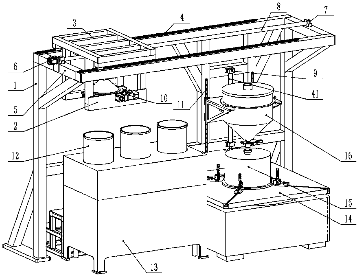
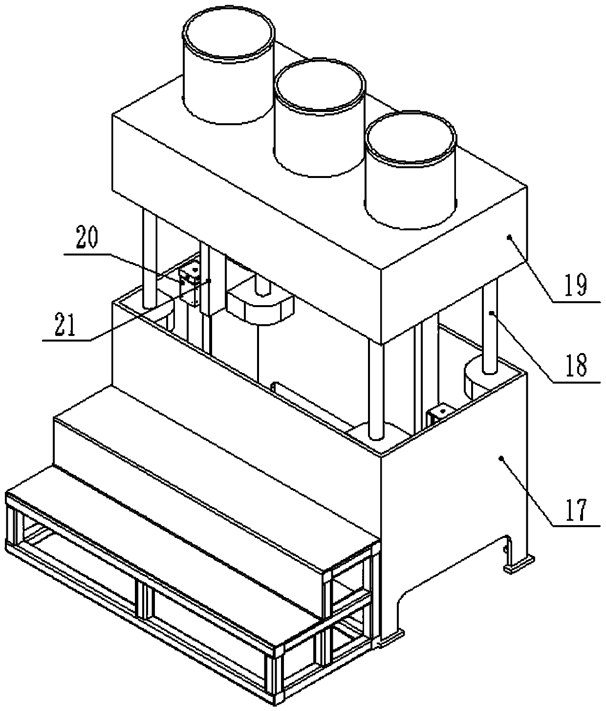
[0034] Such as Figure 1-9 As shown, an automatic compensation filling device for isostatic pressing of energetic materials, including a frame 1, a barrel gripper assembly, a lifting table assembly 13, a barrel 12, an elevating hopper assembly, a hopper 16, and an elastic mold 15 and the vibrating table 14, the frame 1 is used as the overall support and positioning of the system, and the lower bottom plate is fixed to the ground; the barrel 12 is used to store energetic material powder raw materials. The hopper 16 is used for the temporary storage and automatic feeding of energetic material powder, which can move up and down, and an automatic slide valve 32 is installed at the bottom. The lifting table assembly 13 and the vibrating table 14 are installed in one side of the frame 1, the barrel 12 is placed on the upper part of the lifting table assembly 13, the elastic mold 15 is installed on the vibrating table 14, and the elevating hopper assembly is slidably installed on the...

Embodiment 2

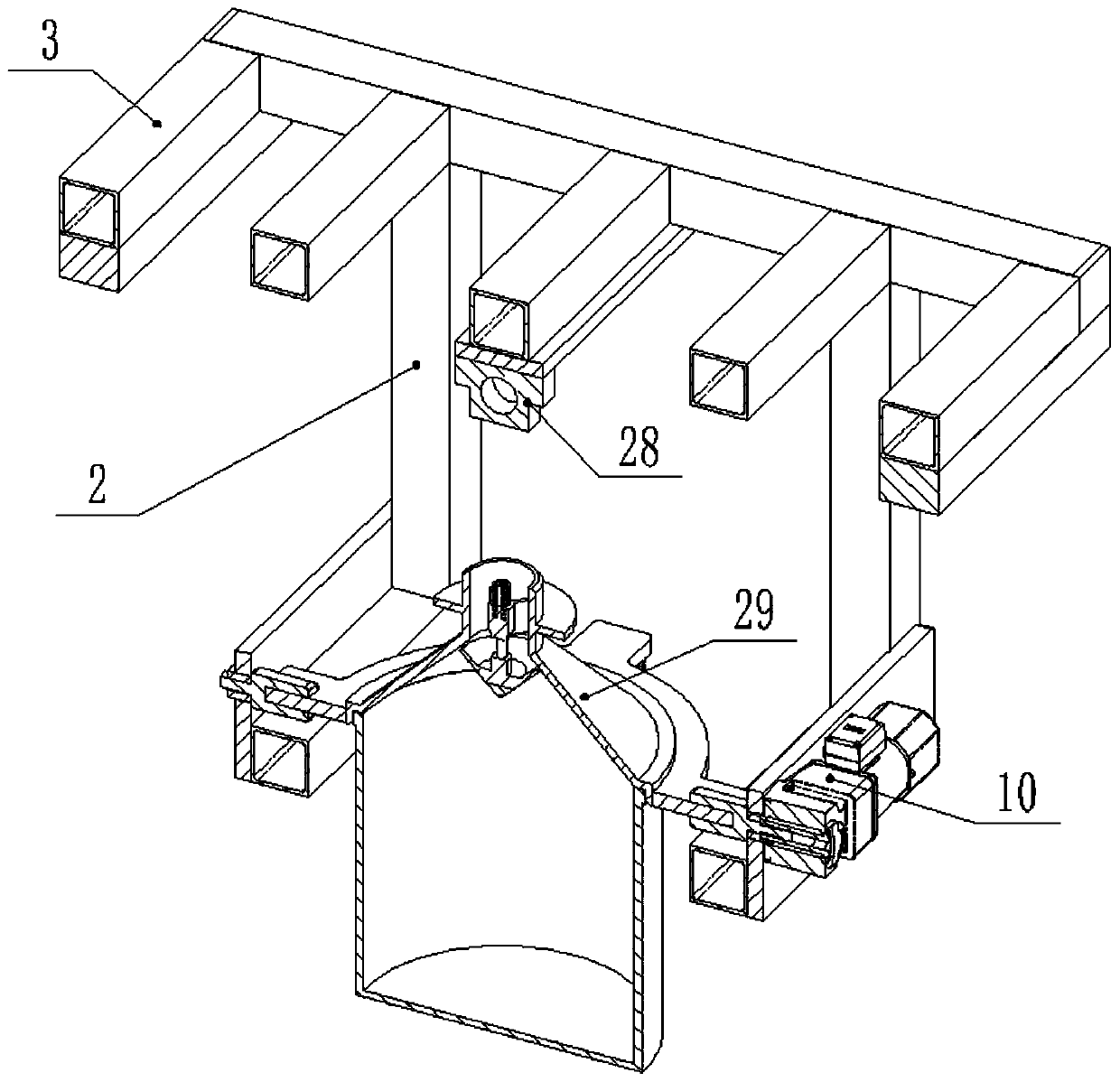
[0037] Such as image 3 As shown, this embodiment is further optimized on the basis of Embodiment 1, and the similarities will not be repeated. In this embodiment, the barrel gripper assembly includes a first displacement assembly, a first mounting frame, a material The barrel positioning plate 22, the claw assembly and the sealing cover 29, the first displacement assembly is installed on the top of the frame 1, the first installation frame is movably installed on the first displacement assembly, the barrel positioning plate 22 is circular, and the barrel The inner ring of the positioning plate 22 is used to fasten on the barrel 12, and the barrel positioning plate 22 is equipped with two oppositely arranged gripper assemblies for grabbing the barrel 12 and two oppositely arranged gripper assemblies for driving the barrel 12. The rotating shaft 23 turned over by the positioning plate 22, the connection line between the two claw assemblies and the two rotating shafts 23 is a cr...

Embodiment 3

[0041] Such as Figure 4 As shown, this embodiment is further optimized on the basis of Embodiment 2, and the similarities will not be repeated. In this embodiment, the claw assembly includes a cylinder 24, an arc matched with the side wall of the barrel 12 Shaped pressure head 25 and anti-static rubber pad 26, cylinder 24 is installed on the bottom of barrel positioning plate 22, arc-shaped pressure head 25 is installed on the telescopic rod of cylinder 24, anti-static rubber pad 26 is installed on the arc-shaped pressure head 25 . This embodiment mainly provides the specific structure of the holding claw assembly. The arc-shaped pressure head 25 expands and contracts under the action of the cylinder 24 to complete the holding and fixing of the barrel 12. And anti-static rubber pad 26 one is to play the effect of anti-static, plays the effect of safety, the 2nd, can make arc-shaped indenter 25 and barrel 12 side walls fasten more closely, contributes to the hugging of barrel...


PUM


Abstract

The invention discloses an automatic compensation filling device for isostatic press moulding of energetic materials, and belongs to the technical field of energetic materials. The automatic compensation filling device comprises a rack, a material cylinder gripper assembly, a lifting material platform assembly, material cylinders, a lifting hopper assembly, a hopper, an elastic mould and a vibration platform, the lifting material platform assembly and the vibration platform are mounted in one side of the rack, the material cylinders are placed on the upper part of the lifting material platformassembly, the elastic mould is mounted on the vibration platform, the lifting hopper assembly is slidably mounted on the position, above the elastic mould, of the rack, the hopper is mounted on the lifting hopper assembly, a bottom discharging outlet of the hopper is opposite to a feeding inlet of the elastic mould, and the material cylinder gripper assembly is slidably mounted at the top of therack and used for gripping the material cylinders and moving the material cylinders to the position above a top falling opening of the hopper. The automatic compensation filling device is novel in structure, adopts a brand-new design mode, and realizes automatic feeding, falling and filling operation of the energetic materials, and the phenomena of dust raising and powder leakage in the filling process are effectively eradicated.

Description

technical field [0001] The invention relates to the technical field of energetic materials, in particular to an automatic compensating filler device for isostatic pressing of energetic materials. Background technique [0002] Compared with traditional energetic material molding products, isostatic pressing has unique advantages such as high and uniform product density and near-net molding. The basic principle is to place the powder energetic material pre-packaged in an elastic mold such as rubber or plastic in a closed container filled with liquid, and the deformation of the elastic mold when it is subjected to the pressure of the isotropic liquid medium is transmitted to the mold. Energetic material is powdered so that it can be compacted into a compact body or part with a certain density and strength. [0003] Since the surface of the outer mold is subjected to the same pressure during the isostatic pressing process, in order to avoid the uneven shrinkage of different par...

Claims


Application Information

Patent Timeline
Patent Type & Authority Applications(China)
IPC IPC(8): B29C43/34B29C43/58B29C43/02
CPCB29C43/02B29C43/34B29C43/58B29C2043/3427B29C2043/3494B29C2043/5875
Inventor 杨宝刚贺建华韩超张锋陈学平张剑朱兴虎姚松
Owner INST OF CHEM MATERIAL CHINA ACADEMY OF ENG PHYSICS
Learn More