Circular PU air filter element production method

A production method and air filter technology, applied in the production field of circular PU air filter, can solve the problems of long preparation time, high cost, low production efficiency, etc., to improve quality stability, reduce raw material waste, and reduce labor intensity. Effect

Active Publication Date: 2020-06-12
柳州日高滤清器有限责任公司
View PDF6 Cites 1 Cited by
  • Summary
  • Abstract
  • Description
  • Claims
  • Application Information

AI Technical Summary

Problems solved by technology

[0002] At present, the production process of large circular PU air filter products (more than 200mm in diameter and more than 350mm in height) of most domestic air filter manufacturers is not highly automated, and most of the processes are in a manual state, that is, each process is carried out separately. , continuous production cannot be realized, the existing intermittent production method has low production efficiency, high labor intensity of workers, poor quality control, long preparation time before production, and relatively large waste of materials. Big and other deficiencies
[0003] The filter production lines of some foreign-funded enterprises use professional robots for production, which can solve some shortcomings such as low production efficiency and high labor intensity of workers. However, the production line structure adopted by them is only suitable for large-scale single-variety production, and mold replacement is inconvenient. It is not conducive to the production of small batches and multi-variety products, and the cost is high, which ordinary small and medium-sized enterprises cannot afford

Method used


Image

  • Circular PU air filter element production method
  • Circular PU air filter element production method
  • Circular PU air filter element production method

Examples


Embodiment 1

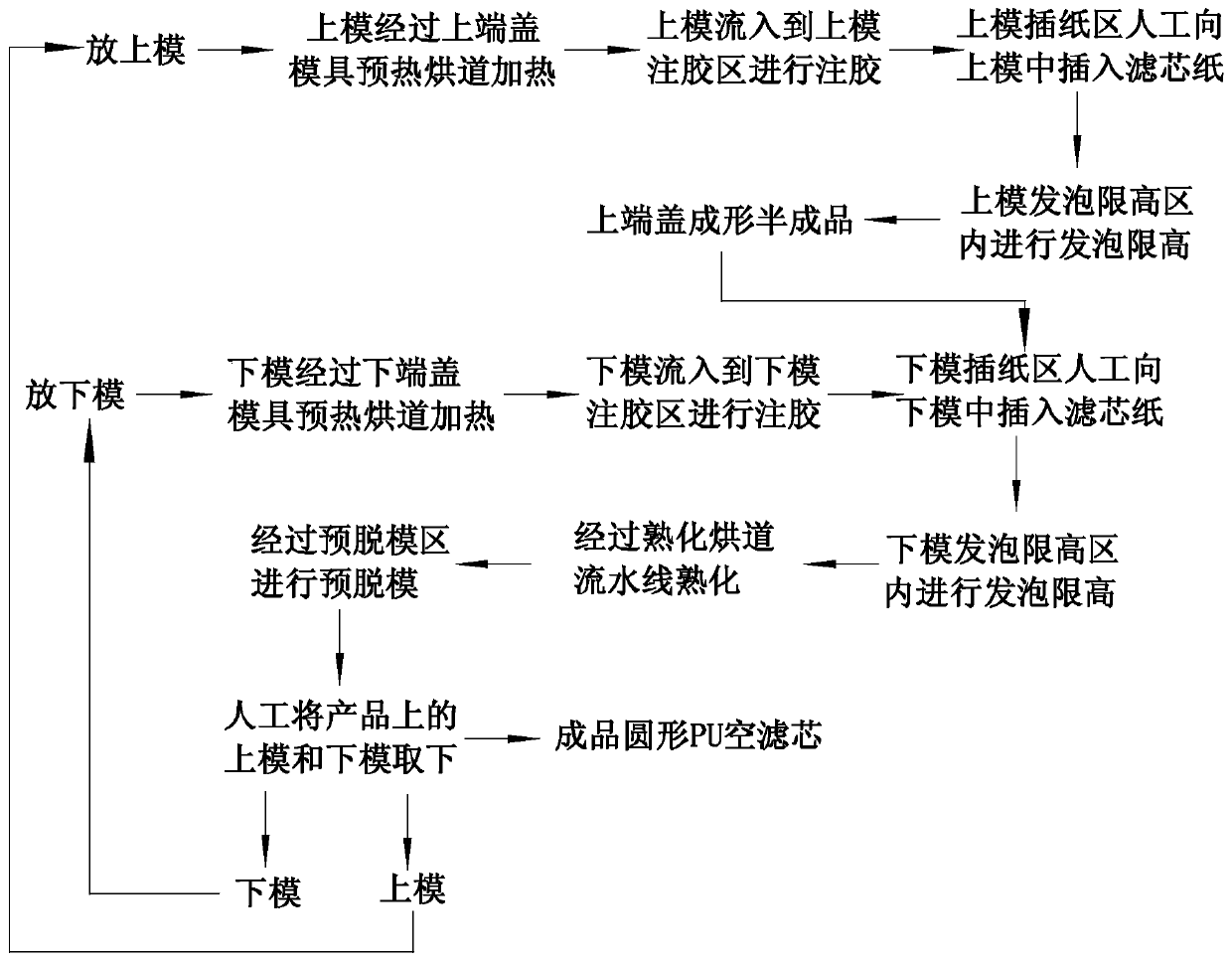
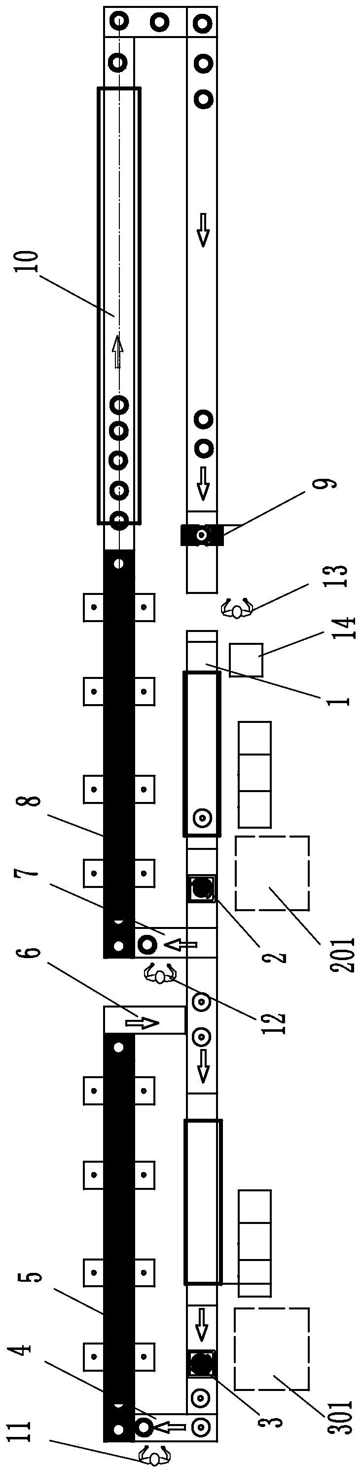
[0052] Embodiment 1: a kind of circular PU air filter core production method, the production device that adopts is circular PU air filter core production line (such as Figure 3-Figure 4 shown), including the mold conveying line 1, the upper end cover glue injection and foaming line, the lower end cover glue injection and foaming line, the curing oven line 10 and the pre-demolding area 9, and the mold conveying line includes the upper and lower mold conveying lines 101 And the upper mold delivery line 102 of the lower floor, that is, the mold delivery line adopts an original upper and lower double-layer mold delivery structure, so that the upper and lower molds can be put in one place at the same time. The upper end cover glue injection and foaming line includes an upper mold glue injection area 3, an upper mold paper insertion area 4, an upper mold foaming solidification heat preservation height limit area 5 and an extended buffer line section 6 after the upper end cover is fo...


PUM

PropertyMeasurementUnit
diameteraaaaaaaaaa
diameteraaaaaaaaaa
heightaaaaaaaaaa

Abstract

The invention relates to a circular PU air filter element production method including the following steps that firstly, upper molds are put onto a mold conveying assembly line to be heated and then flow into an upper mold glue injection area to be subjected to glue injection, the upper molds completely subjected to glue injection flow into an upper mold paper insertion area to be subjected to manual paper insertion, and then upper end cover formed filter element semi-finished products are obtained after the upper molds pass an upper mold foaming solidifying heat preservation and height limitation area; secondly, the upper molds are continuously put onto the mold conveying assembly line, and the first step is unceasingly repeated; thirdly, lower end covers are formed at the other ends of the semi-finished products, and the forming process is basically the same as that in the first step; and fourthly, after curing and demolding, finished product circular PU air filter elements are obtained. According to the circular PU air filter element production method, the circular PU air filter elements are produced through a continuous production method, assembly line production is adopted forkey working procedure points, including glue injection, foaming solidifying heat preservation and height limitation, curing heat preservation and pre-demolding, in PU air filter element production, the production efficiency can be improved, the labor intensity can be lowered, raw material waste can be reduced, and quality stability can be improved.

Description

technical field [0001] The invention relates to a production method of a filter element, in particular to a production method of a circular PU air filter element. Background technique [0002] At present, the production process of large circular PU air filter products (more than 200mm in diameter and more than 350mm in height) of most domestic air filter manufacturers is not highly automated, and most of the processes are in a manual state, that is, each process is carried out separately. , continuous production cannot be realized, the existing intermittent production method has low production efficiency, high labor intensity of workers, poor quality control, long preparation time before production, and relatively large waste of materials. Big and other deficiencies. [0003] The filter production lines of some foreign-funded enterprises use professional robots for production, which can solve some shortcomings such as low production efficiency and high labor intensity of wo...

Claims


Application Information

Patent Timeline
Patent Type & Authority Applications(China)
IPC IPC(8): B29C44/02B29C44/34B29C44/38B29L31/14
CPCB29C44/02B29C44/34B29C44/3415B29C44/38B29L2031/14
Inventor 钟康海韦宏韦尚勇王飞罗桂泉韦华
Owner 柳州日高滤清器有限责任公司
Why Eureka
Try Eureka