Petroleum pipeline conveying device

A technology for conveying devices and oil pipelines, applied in the direction of conveyors, conveyor objects, transportation and packaging, etc., to achieve the effects of improving stability, reducing labor force, and improving applicability

Active Publication Date: 2020-06-12
江苏赛弗道管道股份有限公司
8 Cites 8 Cited by

AI-Extracted Technical Summary

Problems solved by technology

[0003] The purpose of the present invention is to provide a petroleum pipeline transportation device, which can effectively solve the problems of manual transportation in the prior art; a transportation line can be forme...

Method used

A kind of petroleum pipeline conveying device of the present invention, when carrying out the transportation work of petroleum pipeline, can form a conveyance line by installing the present invention that a plurality of relative settings are arranged, need the clamping conveyance of a plurality of petroleum pipeline conveying devices The mechanism 2 is aligned to ensure that the oil pipeline is continuously transported along a straight line, reducing labor force, improving the stability of handling and the speed of transportation; the present invention is equipped with a clamping and conveying mechanism 2 that can clamp and fix oil pipelines of different sizes to improve Applicability, it is convenient to transport oil pipelines of various sizes, and when transporting longer oil pipelines, the distance between the two clamping and conveying mechanisms 2 can be controlled by the distance regulating mechanism 3, which improves the consignment of oil pipelines Conveying stability, when the distance between the two clamping and conveying mechanisms 2 increases, it can synchronously drive the four curved connecting rods 4 to move outward, and when the four curved connecting rods 4 move outward, they can synchronously drive the four first The auxiliary support mechanism 5 expands outwards. When the four first auxiliary support mechanisms 5 expand outward, the four transmission mechanisms 6 drive the four second auxiliary support mechanisms 7 to expand outward. Mechanism 5 and four second auxiliary supporting mechanisms 7 extend to the four sides of the support mechanism 1, which can improve the stability of the support mechanism of the present invention and reduce the probability of the present invention toppling; the clamping and conveying mechanism 2 needs to be connected Turn on the power to transport the pipeline.
As shown in Figure 1-13, described clamping assembly 205 comprises servomotor 205A, driving sprocket 205B, driven sprocket 205C, axle 205D, clamping conveying roller 205E, gantry 205F and linkage wheel 205G The servo motor 205A is affixed to the gantry 205F; the inner side of the gantry 205F is rotated to cooperate with multiple axles 205D arranged side by side, and one of the axles 205D is fixed in the middle of the multiple axles 205D. The above-mentioned clamping conveying roller 205E, one end of a plurality of the wheel shafts 205D is fixedly connected to one of the linkage wheels 205G respectively, and the plurality of linkage wheels 205G are connected through a synchronous toothed belt transmission; the gantry 205F is fixedly connected to At the inner end of the two sliding shafts 204E; the inner end of the adjusting screw 204B is rotatably fitted on the gantry 205F through a bearing with seat; the driving chain is fixedly connected to the output shaft of the servo motor 205A The driving sprocket 205B is connected to the driven sprocket 205C through a chain transmission; the driven sprocket 205C is fixedly connected to the other end of the wheel shaft 205D. The conventional state of the clamping assembly 205 is the state shown in Fig. 4 and Fig. 5, which is used for the transportation of oil pipelines. At this tim...

Abstract

The invention relates to the technical field of pipeline conveying, and particularly relates to a petroleum pipeline conveying device. The petroleum pipeline conveying device comprises a support mechanism, clamping conveying mechanisms, a distance adjusting and controlling mechanism, bent connecting rods, first auxiliary supporting mechanisms, a transmission mechanism and a second auxiliary supporting mechanism, wherein the top end of the support mechanism is fixedly connected with the distance adjusting and controlling mechanism; the distance adjusting and controlling mechanism is in transmission connection with the two clamping conveying mechanisms; the two clamping conveying mechanisms are symmetrically arranged at the two ends of the support mechanism in a sliding fit manner; the two ends of each of the two clamping conveying mechanisms are fixedly connected with the upper end of one bent connecting rod; the lower ends of the four bent connecting rods are fixedly connected with thefirst auxiliary supporting mechanisms; and a carrying line can be formed by installing the multiple oppositely-arranged petroleum pipeline conveying devices, pipelines are continuously conveyed in the horizontal direction, labor force is reduced, and the carrying stability and the conveying speed are improved.

Application Domain

Technology Topic

Image

  • Petroleum pipeline conveying device
  • Petroleum pipeline conveying device
  • Petroleum pipeline conveying device

Examples

  • Experimental program(9)

Example Embodiment

[0037] Specific embodiment one:
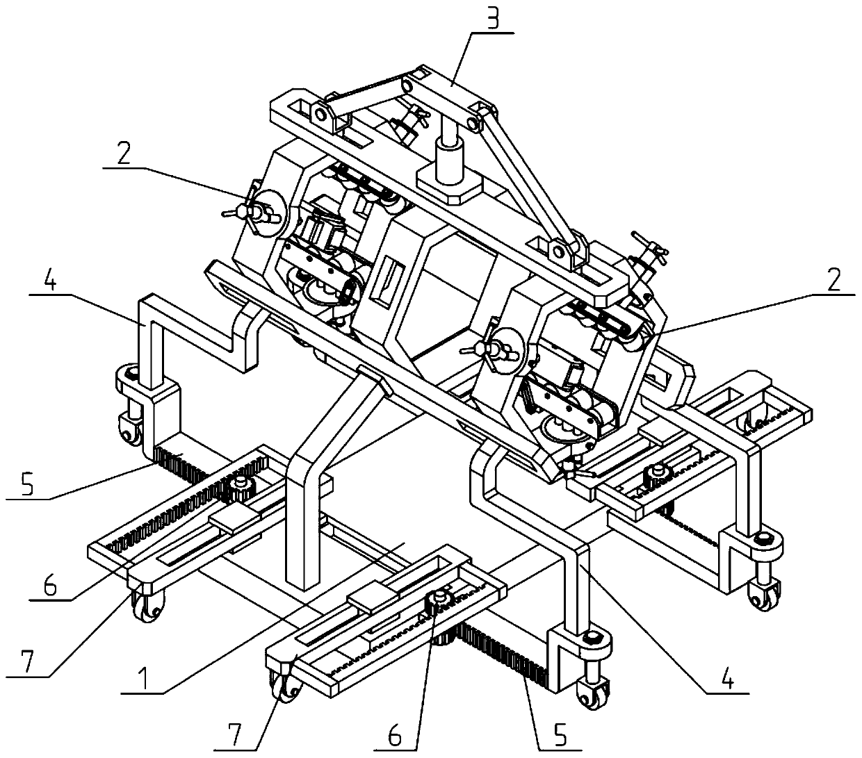
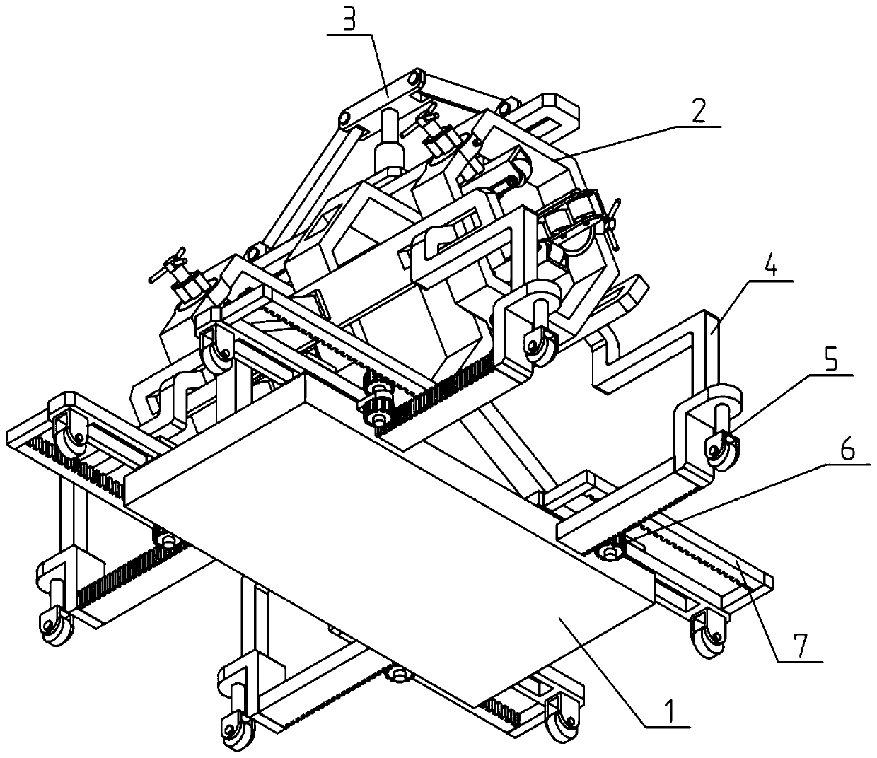
[0038] Such as Figure 1-13 As shown, the petroleum pipeline transportation device includes a bracket mechanism 1, a clamping and conveying mechanism 2, a spacing adjusting mechanism 3, a bending link 4, a first auxiliary supporting mechanism 5, a transmission mechanism 6 and a second auxiliary supporting mechanism 7. The bracket The top end of the mechanism 1 is fixedly connected to the spacing regulating mechanism 3; the spacing regulating mechanism 3 is drivingly connected to the two clamping and conveying mechanisms 2; the two clamping and conveying mechanisms 2 are symmetrically slidingly fitted to the bracket mechanism 1 Both ends; the two ends of the clamping and conveying mechanism 2 are respectively fixed to the upper end of one of the bending links 4, and the lower ends of the four bending links 4 are respectively fixed to the first auxiliary support mechanism 5; The four first auxiliary support mechanisms 5 are respectively slidably fitted on both sides of the left and right ends of the bracket mechanism 1; the four first auxiliary support mechanisms 5 respectively engage and drive one transmission mechanism 6, four The transmission mechanism 6 is fixedly connected to the support mechanism 1, and the four transmission mechanisms 6 are respectively engaged and connected to one of the second auxiliary support mechanisms 7; the four second auxiliary support mechanisms 7 are respectively connected to the The two sides of the front and rear ends of the support mechanism 1.
[0039] An oil pipeline transportation device of the present invention can be used to form a transport line by installing a plurality of opposedly arranged oil pipeline transportation devices during the transportation work of the oil pipeline. Alignment ensures the continuous transportation of oil pipelines along a straight line, reduces labor, improves transportation stability and transportation speed; the invention is equipped with a clamping and transportation mechanism 2 that can clamp and fix oil pipelines of different sizes, which improves applicability. It is convenient to transport oil pipelines of various sizes, and when transporting longer oil pipelines, the spacing between the two clamping transport mechanisms 2 can be controlled by the spacing adjustment mechanism 3 to increase the stability of the oil pipeline consignment As the distance between the two clamping and conveying mechanisms 2 increases, it can simultaneously drive the four bending links 4 to move outwards, and when the four bending links 4 move outwards, it can drive the four first auxiliary support mechanisms synchronously 5 Perform the expansion movement to the outside. When the four first auxiliary support mechanisms 5 are expanded to the outside, the four second auxiliary support mechanisms 7 can be driven to expand outward through the four transmission mechanisms 6 and the four first auxiliary support mechanisms 5 and The four second auxiliary support mechanisms 7 are extended to the four sides of the support mechanism 1, which can improve the stability of the support mechanism of the support mechanism of the present invention and reduce the probability of dumping of the present invention; the clamping and conveying mechanism 2 needs to be powered on. Transport the pipeline.

Example Embodiment

[0040] Specific implementation manner two:
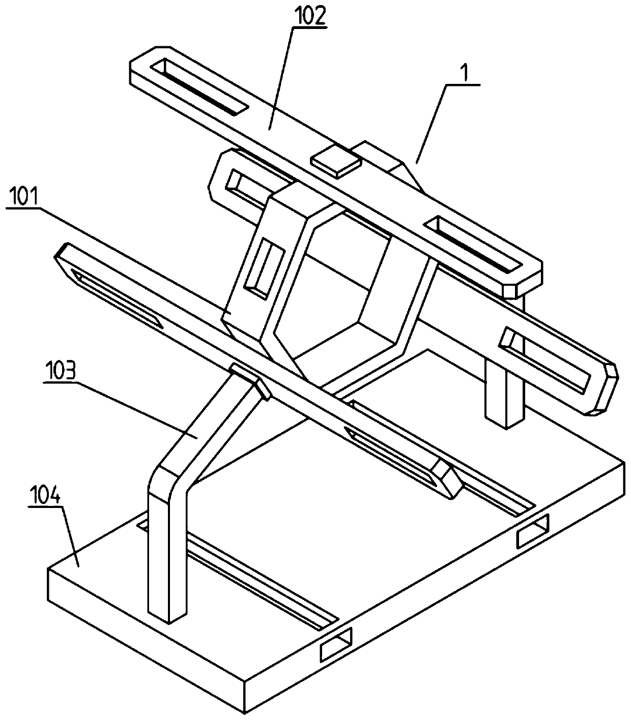
[0041] Such as Figure 1-13 As shown, the support mechanism 1 includes a fixed hexagonal frame 101, a guide frame plate 102, a curved support 103, and a support base 104; the outer surface of the fixed hexagonal frame 101 is evenly fixed to three guide frame plates 102 The two guide frame plates 102 at the lower end are respectively fixed to the top end of one of the curved brackets 103, and the bottom ends of the two curved brackets 103 are symmetrically fixed to the two ends of the bracket base 104; A guide slideway is respectively provided at both ends of the guide frame plate 102.

Example Embodiment

[0042] Specific implementation manner three:
[0043] Such as Figure 1-13 As shown, the distance control mechanism 3 includes an electric telescopic rod 301, a lifting control board 302, a tilt link 303, and a linkage seat 304; the fixed end of the electric telescopic rod 301 is fixedly connected to the guide frame plate 102 at the upper end The movable end of the electric telescopic rod 301 is fixedly connected to the middle of the lifting control board 302; the two ends of the lifting control board 302 are respectively connected to the inner end of the tilt link 303, two The outer ends of the inclined connecting rods 303 are respectively connected to one of the linkage seats 304 in rotation; two of the linkage seats 304 are fixedly connected to the two clamping and conveying mechanisms 2 one by one. The electric telescopic rod 301 can drive the lifting control board 302 to move up and down after being powered on. When the lifting control board 302 moves up and down, it can drive the inner ends of the two inclined links 303 to move up and down. The outer ends of the two inclined links 303 can Pulling will push the two linkage seats 304 to move inside and outside, thereby driving the two clamping and conveying mechanisms 2 on both sides to move toward or away from the three guide frame plates 102 to complete the adjustment of the distance between the two clamping and conveying mechanisms 2 .

PUM

no PUM

Description & Claims & Application Information

We can also present the details of the Description, Claims and Application information to help users get a comprehensive understanding of the technical details of the patent, such as background art, summary of invention, brief description of drawings, description of embodiments, and other original content. On the other hand, users can also determine the specific scope of protection of the technology through the list of claims; as well as understand the changes in the life cycle of the technology with the presentation of the patent timeline. Login to view more.

Similar technology patents

Multi-coin sorting and packing device

InactiveCN105976500AHigh precisionLabor savingCoin testingMagnet
Owner:SHANGHAI UNIV OF ENG SCI

Classification and recommendation of technical efficacy words

  • Improve stability
  • Labor saving

Surgical ligature clip

InactiveUS20080312670A1Improve stabilityAvoid spaceWound clampsOrthodontic ligatureArm moving
Owner:AESCULAP AG

Pitaya high-quality and high-yield cultivation method adopting water and fertilizer integrated fertigation technology

InactiveCN104737743ALabor savingSolve labor difficultiesFertilising methodsHorticultureEchinocereus enneacanthusFrost
Owner:GUANGXI JIN HONG GUO AGRI COMPREHENSIVE DEV CO LTD
Why Eureka
Try Eureka