Thin-wall type house structure and construction method thereof

A house and thin-walled technology, applied in the thin-walled house structure and its construction field, can solve the problems that cannot be effectively solved, insufficient bulkiness of thermal insulation materials, difference in thermal insulation performance, etc. and durable performance

Pending Publication Date: 2020-06-12
黑龙江中科工程管理咨询有限公司
View PDF0 Cites 2 Cited by
  • Summary
  • Abstract
  • Description
  • Claims
  • Application Information

AI Technical Summary

Problems solved by technology

Thirdly, the insulation layer of the portal frame structure is outside the main structure. Due to the extrusion of the outer plate and the secondary structure, the bulkiness of th

Method used


Image

  • Thin-wall type house structure and construction method thereof
  • Thin-wall type house structure and construction method thereof
  • Thin-wall type house structure and construction method thereof

Examples


specific Embodiment approach 1

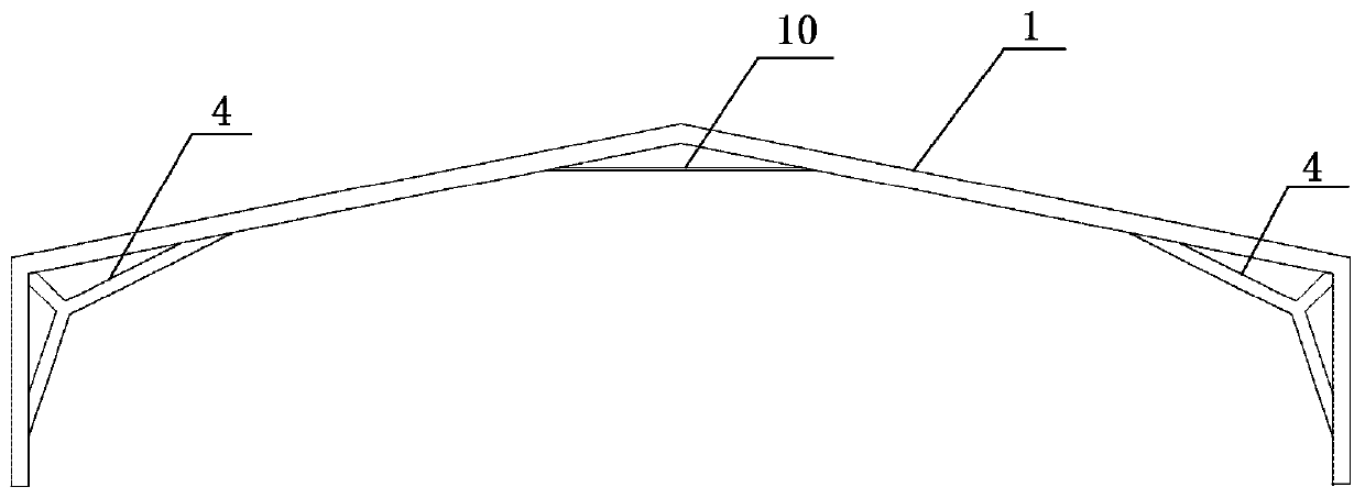
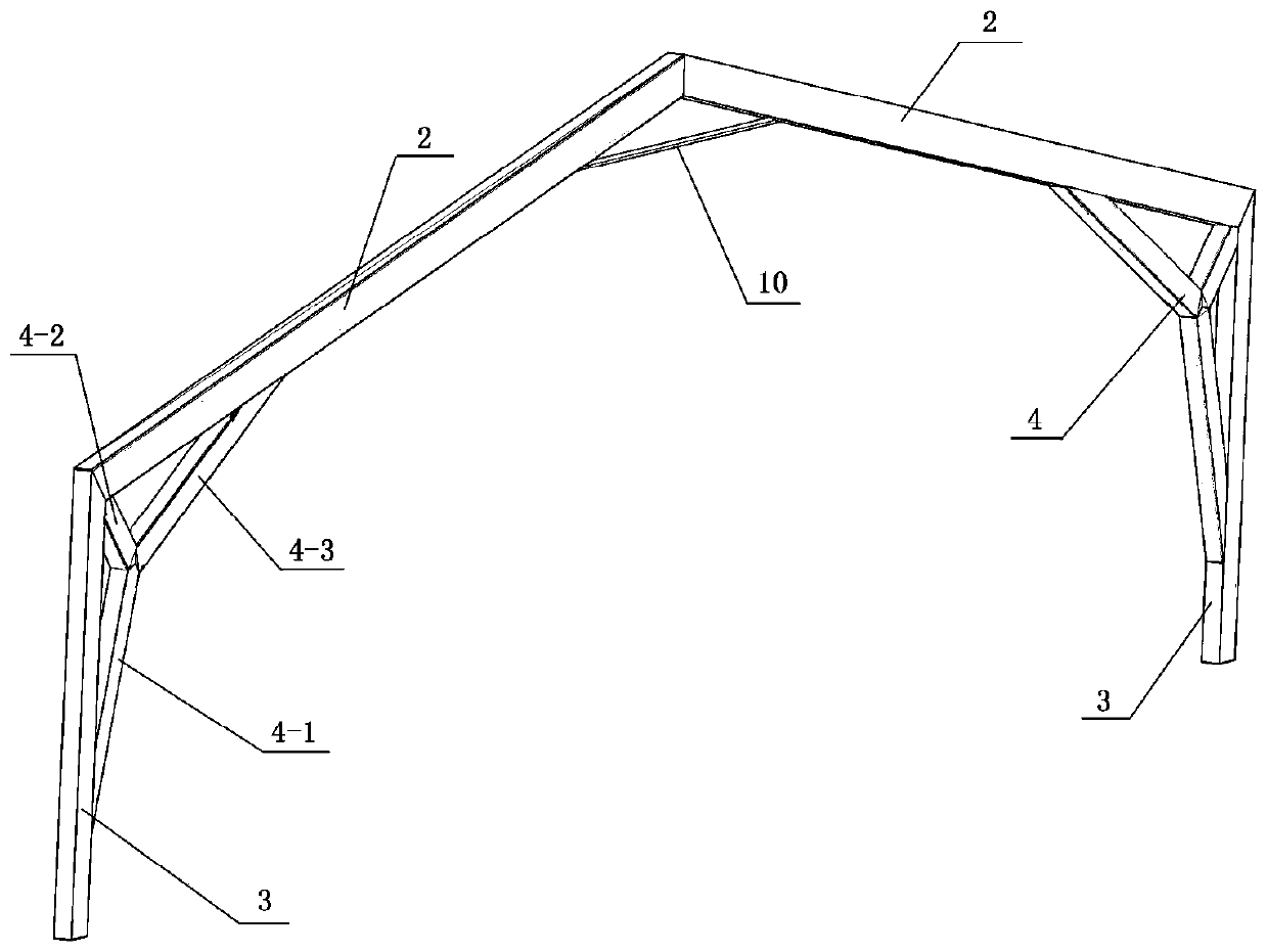
[0040] Specific implementation mode one: combine figure 1 , figure 2 , image 3 , Figure 4 , Figure 5 , Image 6 , Figure 7 , Figure 8 , Figure 9 , Figure 10 , Figure 11 , Figure 12 , Figure 13 with Figure 14 Describe this embodiment, this embodiment includes a main frame body 1 and a support member, the main frame body 1 includes two beams 2 and two columns 3, the two beams 2 are arranged obliquely side by side, the high ends of the two beams 2 are connected, the two beams 2 The lower ends of each beam 2 are respectively provided with a column 3, and each column 3 is fixedly connected with the end of the corresponding beam 2, the beam 2 is a beam of equal cross section, the column 3 is a cylinder of equal section, and the supporting parts include beams for adding For the haunches and the end corner haunches, the beam haunches are arranged at the high ends of the two beams 2 , and the end corner haunches are arranged between each beam 2 and its correspon...

specific Embodiment approach 2

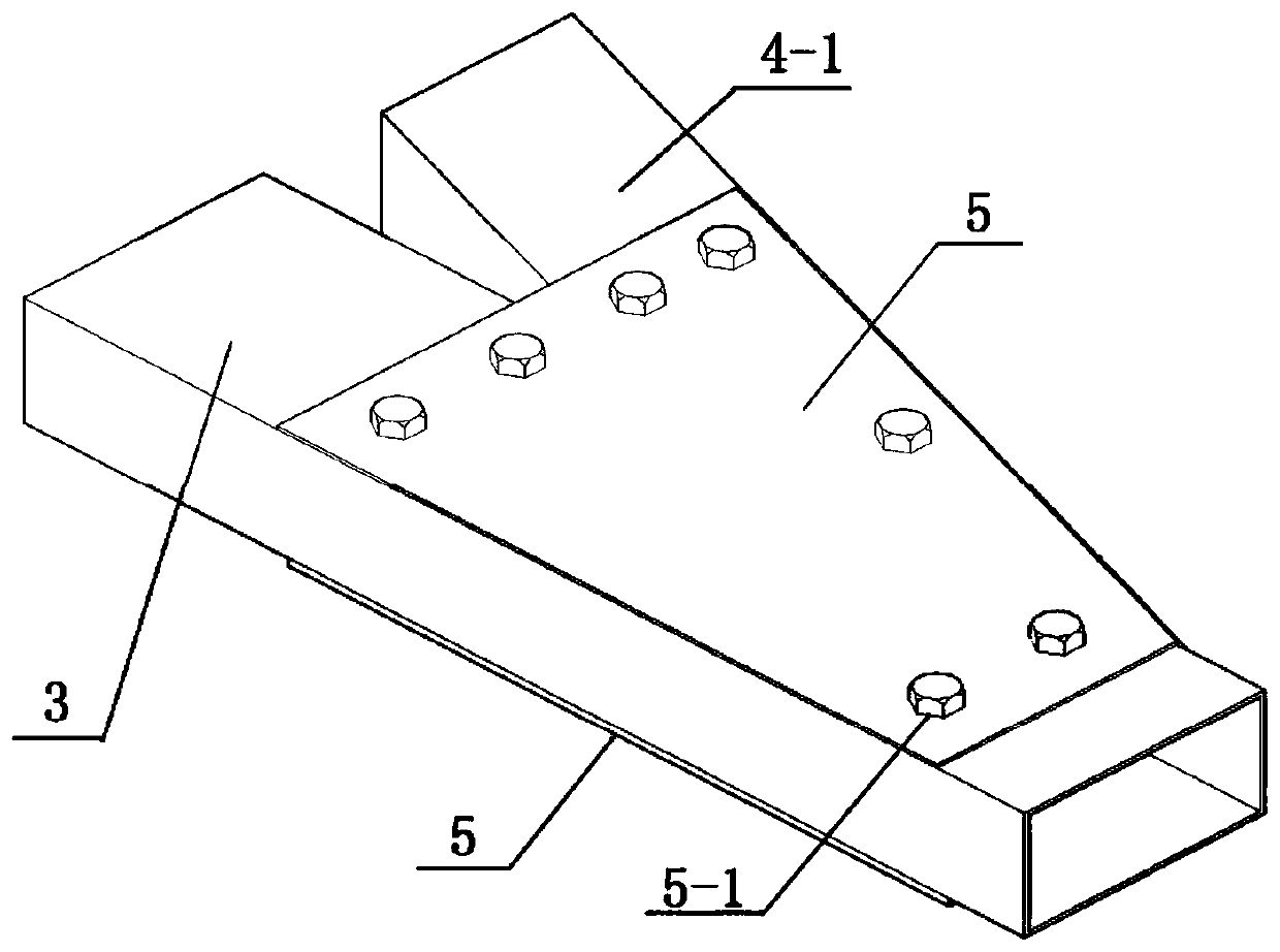
[0042] Specific embodiment 2: This embodiment is a further limitation of specific embodiment 1. The end angle adding armpit is a trident support body 4 or a pressure rod 11 for the end angle, such as figure 1 with figure 2 As shown, when the end angle adding armpit is the trident support body 4 for the end angle, the trident support body 4 for the end angle includes a first support rod 4-1, a second support rod 4-2, and a third support rod 4-3 And two three-fork connecting pieces 4-4, one end of the first support rod 4-1, one end of the second supporting rod 4-2 and one end of the third supporting rod 4-3 pass through two three-fork connecting pieces 4-4 Detachable connection, the other end of the first support rod 4-1 is detachably connected to the column 3, the other end of the second support rod 4-2 is detachably connected between the beam 2 and the column 3, the third support rod 4- The other end of 3 is detachably connected on the beam 2.

[0043] This embodiment has m...

specific Embodiment approach 3

[0051] Specific embodiment 3: This embodiment is a further limitation of specific embodiment 1 or 2, and the said beam with axillary member is a tie rod 10 or a vertical trident support body 12, such as figure 1 , figure 2 , Figure 12 with Figure 15 As shown, when the beam haunching member is a tie rod 10 , the tie rod 10 is horizontally arranged between two beams 2 .

[0052] Such as Figure 13 with Figure 14 As shown, when the armpit for the beam is a vertical three-prong support body 12, the vertical three-prong support body includes a first support column 12-1 and two first oblique bars 12-2, and the first support column 12-1 vertically The two first slanting rods 12-2 are arranged obliquely on both sides of the first support column 12-1 respectively, and one end of each first slanting rod 12-2 is connected to the first support The column 12-1 is fixedly connected, and the other end of each first slanting rod 12-2 is fixedly connected with the adjacent beam 2.


PUM

PropertyMeasurementUnit
Wall thicknessaaaaaaaaaa

Abstract

The invention discloses a thin-wall type house structure and construction method thereof, and belongs to the field of buildings. An existing house structure is heavy in weight, high in manufacturing cost, high in processing difficulty and complex in installation process. The house structure disclosed by the invention comprises a main frame body and a supporting piece, wherein the main frame body comprises two cross beams and two stand columns, the two cross beams are obliquely arranged in parallel, the high ends of the two cross beams are connected, the lower ends of the two cross beams are correspondingly provided with vertical columns, and each stand column is fixedly connected with the end part of the corresponding cross beam; the cross beams are equal-cross-section bodies, and the stand columns are equal-cross-section bodies; and the supporting piece comprises a beam haunching piece and an end angle haunching piece, the beam haunching piece is arranged at the high ends of the two cross beams, and the end angle haunching piece is arranged between each cross beam and the corresponding stand column.

Description

Technical field: [0001] The invention relates to a house structure and a construction method thereof, in particular to a thin-walled house structure and a construction method thereof. Background technique: [0002] Today's light industrial workshops and warehouse buildings generally adopt the portal frame structure. This structure has a long history, and the calculation theory is mature and reliable. It is recognized by major design companies and construction companies and is widely used. Compared with heavy industrial plants such as metallurgy, this structural form is called light steel structure, but its core components are still hot-rolled H-shaped steel, the thickness of the steel plate is above 8mm, and the weight is not light. is a relative concept. Taking the national standard atlas as an example, the lightest portal frame with a span of 15 meters is 977 kilograms, which is close to one ton. The main structure of an ordinary warehouse also weighs dozens of tons. A s...

Claims


Application Information

Patent Timeline
IPC IPC(8): E04B1/24E04B1/58E04C3/04E04C3/32E04B7/12
CPCE04B1/2403E04B7/12E04B2001/2406E04B2001/2415E04B2001/2418E04C3/04E04C3/32
Inventor 李长青李娜韩昶宋歧富宫占龙刘婷婷李丽娟郭佳斌赵晓彬
Owner 黑龙江中科工程管理咨询有限公司
Why Eureka
Try Eureka