Full-load range precise current-equalizing device

A full-load, range technology, applied in the direction of parallel operation of DC power supplies, can solve the problems of reducing output voltage, limited dynamic adjustment range of current sharing, and raising, etc., to improve reliability, positive social and economic benefits, and simple circuit implementation. Effect

Inactive Publication Date: 2003-06-25
ZTE CORP
View PDF0 Cites 1 Cited by
  • Summary
  • Abstract
  • Description
  • Claims
  • Application Information

AI Technical Summary

Problems solved by technology

The circuit structure of this device is simple, and it consists of a current-sharing controller and an output voltage regulator to form a closed-loop system. Their current-sharing control adjustment method is unidirectional adjustment. The disadvantage of this unidirectional adjustment method is that not all power Modules actively participate in current sharing regulation, but only modules whose output current is larger than the average current actively lower their output voltage, or only modules whose output current is smaller than the average current actively raise their output voltage to achieve current sharing regulation, so the current sharing The dynamic adjustment range is limited, and it is impossible to achieve accurate current sharing with consistent current sharing degree in the whole load range, and can only guarantee the consistent current sharing effect in a certain load range
In order to achieve high-precision current sharing, it is difficult to design the parameters of the current sharing controller with one-way adjustment mode. Sometimes it is only possible to try out the parameters during debugging, and it is difficult to achieve the best current sharing effect.

Method used


Image

  • Full-load range precise current-equalizing device
  • Full-load range precise current-equalizing device
  • Full-load range precise current-equalizing device

Examples


Embodiment Construction

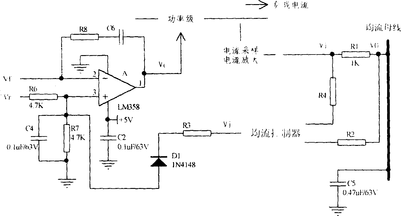
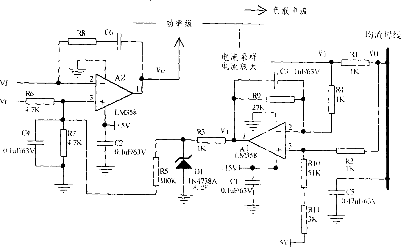
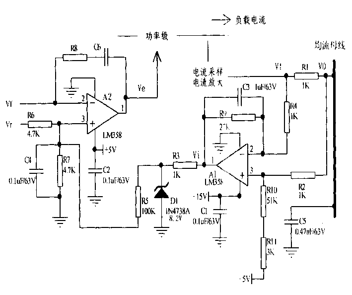
[0014] The present invention will be described in further detail below in conjunction with the accompanying drawings. exist figure 1 The voltage error amplifier A that adjusts the output of the power module is generally a proportional integral link. Its input is the output voltage feedback Vf and the output voltage reference Vr, and its output is the voltage error signal Ve for adjusting the duty cycle of the power stage conversion circuit. From figure 1 It can be seen that the reference input terminal of the voltage error amplifier is affected by the output Vi of the current sharing controller. V1 is the voltage signal reflecting the output current of the module obtained after sampling and amplifying the output current of the power supply, which is used as an input of the current sharing controller; V0 is the current sharing bus connected to the output current signal of each power supply module through a resistor R1 Obtained above, reflecting the average current value of th...


PUM


Abstract

The current equalizing device as one distributed DC source system includes a voltage error amplifier and a current equalizing controller. In the current equalizing controller, resistor R9 and capacitor C3 are connected parallelly between the inverse input and the output of the op-amp; R10, R11 and + 5V power source constitute a bias circuit connected to the non-inverse input of the op-amp; and R9, R10 and R11 meet the expression of R10+R11=2R9. The current equalizing device is simple, easy to design and debug; can realize the two-way regulation based on average current; has high precision in full load range; may be used in various switching circuit for outputting DC voltage.

Description

technical field [0001] The invention relates to a distributed DC power supply system, in particular to an automatic current sharing device when DC power supply modules with the same output capacity are connected in parallel. Background technique [0002] One of the development directions of the power system is to replace the centralized power supply system with a distributed power system. In the communication power supply system, the distributed power supply system is widely used, that is to say, N+n power supply modules are used in parallel combination, of which N sets are used to supply the current required by the load, and n sets (generally n=1) are redundant modules. It can ensure that the power supply system can still provide 100% load current even if n modules fail at the same time, which increases the fault-tolerant redundant power of the system. In addition, the use of redundancy technology can also realize hot replacement, that is, to replace the failed modules of ...

Claims


Application Information

Patent Timeline
Patent Type & Authority Patents(China)
IPC IPC(8): H02J1/10
Inventor 周建平
Owner ZTE CORP
Why Eureka
Try Eureka