Pixel circuit, driving method thereof and display device

A pixel circuit and sub-circuit technology, applied in the field of display, can solve the problems of brightness difference, uneven display, different OLED drive current, etc., to achieve the effect of eliminating positive charges, improving uniformity, and realizing compensation

Active Publication Date: 2020-06-12
BOE TECH GRP CO LTD +1
View PDF12 Cites 3 Cited by
  • Summary
  • Abstract
  • Description
  • Claims
  • Application Information

AI Technical Summary

Problems solved by technology

[0004] In the most basic 2T1C pixel circuit, the size of the OLED drive current is related to the gate-source voltage Vgs and the threshold voltage Vth of the driving TFT, and due to the existence of the power supply voltage drop, the gate-source voltage Vgs of the driving TFT at different positions on the array substrate In addition, the low-temperature polysilicon process is immature. Even with the same process parameters, the threshold voltage Vth of the driving TFT produced is also quite different, which makes the Vth of the driving TFT at different positions on the array substrate different, which in turn will lead to OLED. If the driving current is different, the brightness at different positions of the array substrate will also be different, and the display will be uneven.

Method used


Image

  • Pixel circuit, driving method thereof and display device
  • Pixel circuit, driving method thereof and display device
  • Pixel circuit, driving method thereof and display device

Examples


Embodiment Construction

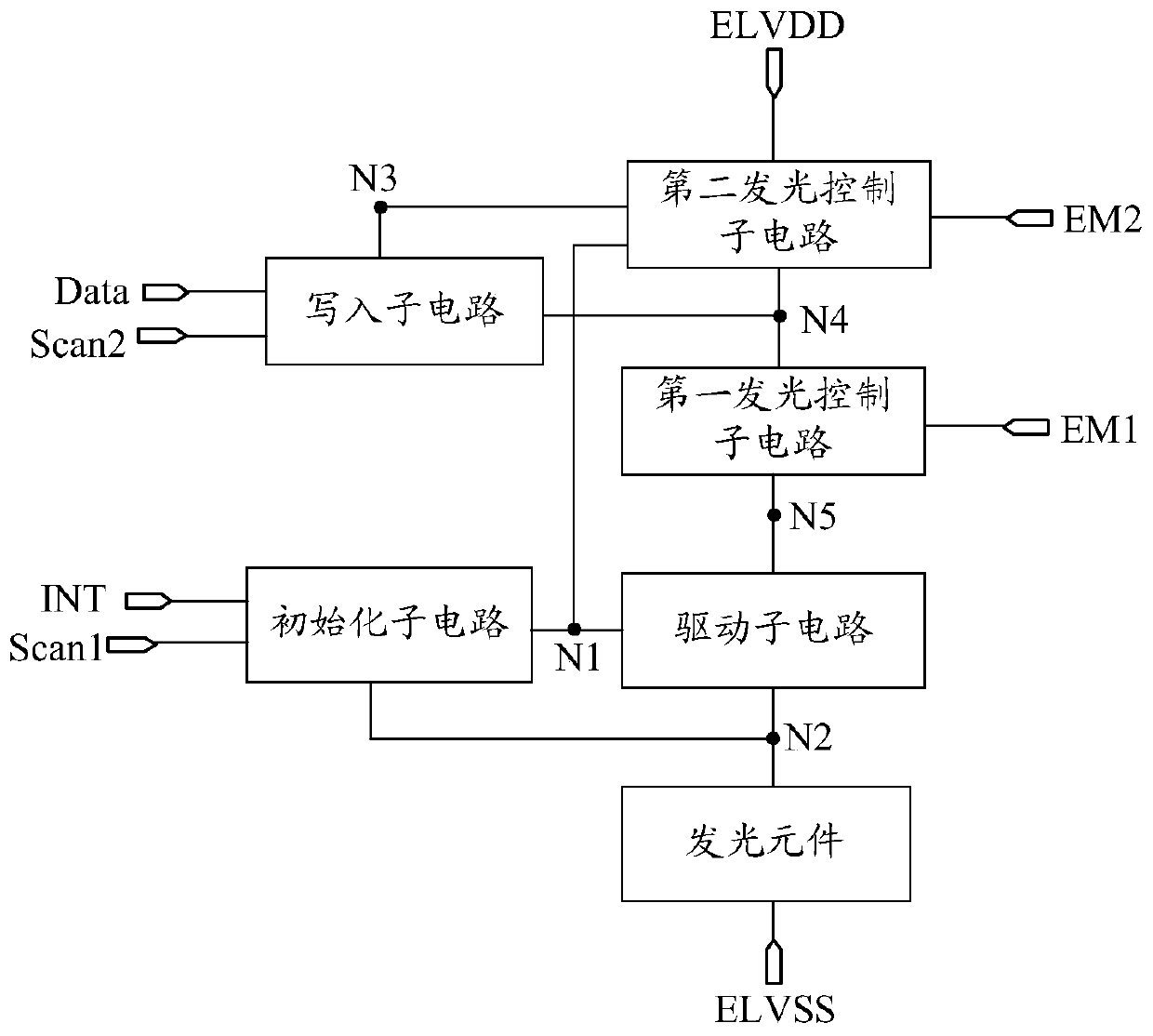
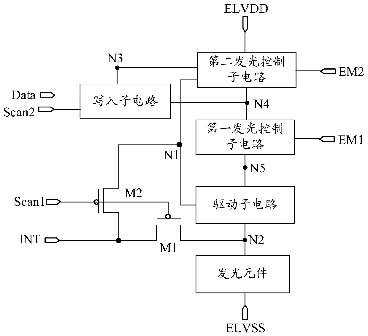
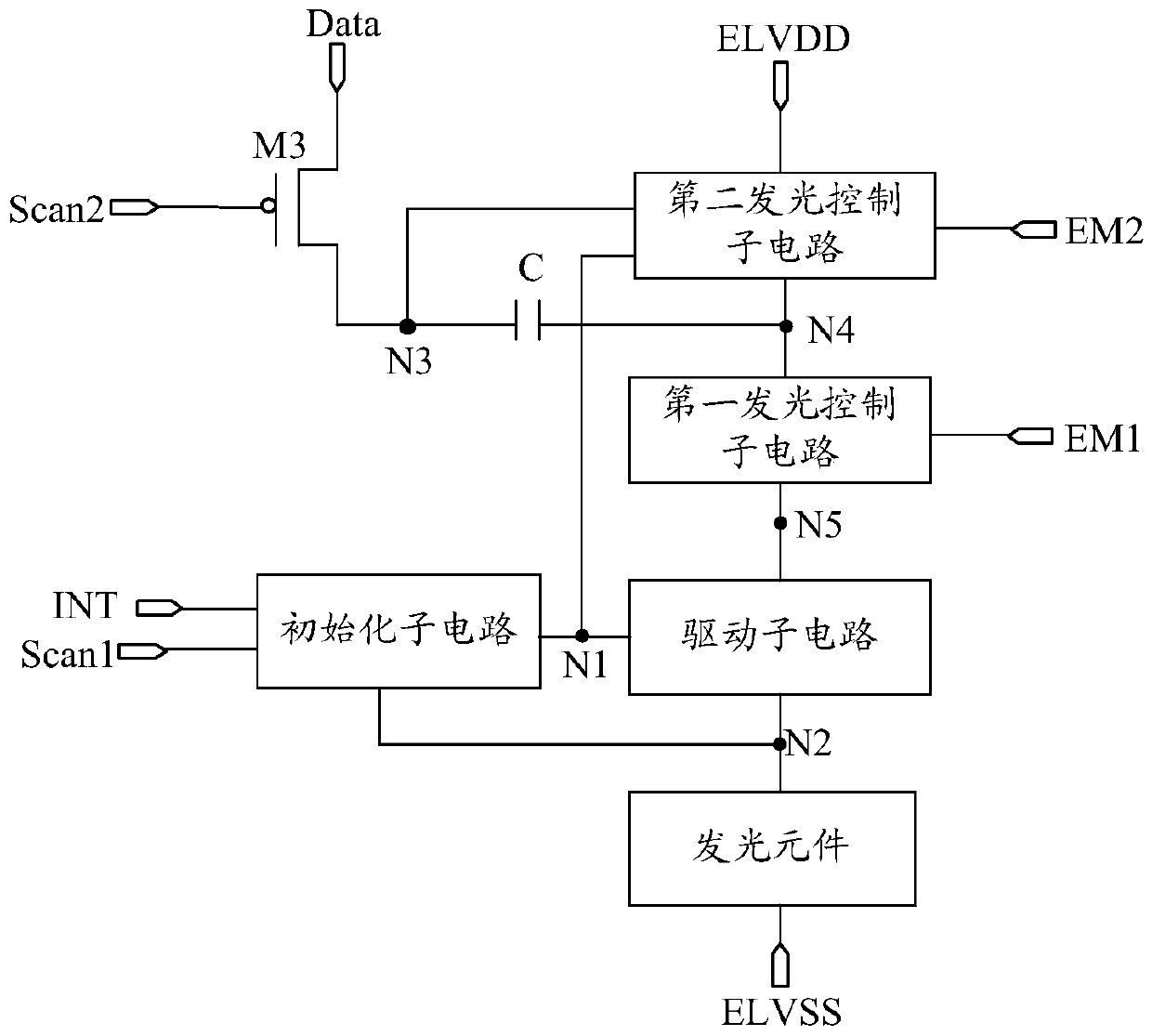
[0034] In order to make the purpose, technical solution and advantages of the present invention more clear, the embodiments of the present invention will be described in detail below in conjunction with the accompanying drawings. It should be noted that, in the case of no conflict, the embodiments in the present application and the features in the embodiments can be combined arbitrarily with each other.

[0035] Unless otherwise defined, the technical terms or scientific terms disclosed and used in the embodiments of the present application shall have the usual meanings understood by those skilled in the field of the present invention. "First", "second" and similar words used in the embodiments of the present application do not indicate any order, quantity or importance, but are only used to distinguish different components. Words such as "comprising" or "comprising" always indicate that the elements or items listed before the word cover the elements or objects listed after th...


PUM


Abstract

The invention relates to a pixel circuit, a driving method thereof and a display device, the pixel circuit comprises an initialization sub-circuit, a write-in sub-circuit, a first light-emitting control sub-circuit, a second light-emitting control sub-circuit and a driving sub-circuit, the initialization sub-circuit provides signals of an initialization signal end for a first node and a second node under the control of a first scanning signal end; the write-in sub-circuit provides a signal of a data input end for a third node under the control of a second scanning signal end, and stores a voltage between the third node and a fourth node; the first light-emitting control sub-circuit controls a fourth node and a fifth node to be conducted under the control of a first light-emitting control signal end; the second light-emitting control sub-circuit provides a signal of a first power supply voltage end for a fourth node under the control of a second light-emitting control signal end, and controls the first node and a third node to be conducted; and the driving sub-circuit performs voltage compensation on the fifth node under the control of the first node and generates a driving currentfor driving the light-emitting element to emit light. According to the invention, the uniformity of the display image is improved.

Description

technical field [0001] The present application relates to but not limited to the field of display technology, and in particular relates to a pixel circuit, a driving method thereof, and a display device. Background technique [0002] In recent years, thanks to the excellent display effect of Active Matrix Organic Light Emitting Diode (AMOLED) displays, the AMOLED industry at home and abroad has developed rapidly. [0003] The ability of AMOLED to emit light is due to the thin film transistor (Thin Film Transistor, TFT) generating a driving current in a saturated state and driving an organic light emitting diode (Organic Light Emitting Diode, OLED) to emit light. The brightness of the OLED is determined by the magnitude of the driving current provided to the OLED device. Proportional, so in order to achieve the best display effect, a larger drive current is required, and low-temperature polysilicon can provide higher electron mobility, so in AMOLED display technology, low-tem...

Claims


Application Information

Patent Timeline
Patent Type & Authority Applications(China)
IPC IPC(8): G09G3/3233
CPCG09G3/3233
Inventor 翁祖伟黄宇鹏翁彬
Owner BOE TECH GRP CO LTD
Why Eureka
Try Eureka