Injection mold facilitating rapid mold releasing

An injection mold and demoulding technology, which is applied in the field of injection molds for quick demoulding. It can solve the problems of taking a lot of time and the product is not easy to separate, and achieve the effect of fast demoulding, low resistance and not easy to be damaged.

Inactive Publication Date: 2020-06-16
徐州海之慧生物技术有限公司
View PDF0 Cites 2 Cited by
  • Summary
  • Abstract
  • Description
  • Claims
  • Application Information

AI Technical Summary

Problems solved by technology

[0004] The purpose of the present invention is to solve the shortcomings in the prior art, such as: traditional injection molds use mold thimbles to cooperate when taking materials, but some plastic products h

Method used


Image

  • Injection mold facilitating rapid mold releasing
  • Injection mold facilitating rapid mold releasing

Examples


Embodiment Construction

[0019] The following will clearly and completely describe the technical solutions in the embodiments of the present invention with reference to the accompanying drawings in the embodiments of the present invention. Obviously, the described embodiments are only some, not all, embodiments of the present invention.

[0020] In describing the present invention, it should be understood that the terms "upper", "lower", "front", "rear", "left", "right", "top", "bottom", "inner", " The orientation or positional relationship indicated by "outside", etc. is based on the orientation or positional relationship shown in the drawings, and is only for the convenience of describing the present invention and simplifying the description, rather than indicating or implying that the referred device or element must have a specific orientation, so as to Specific orientation configurations and operations, therefore, are not to be construed as limitations on the invention.

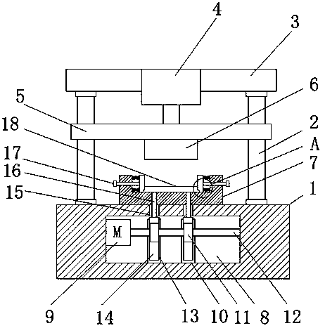
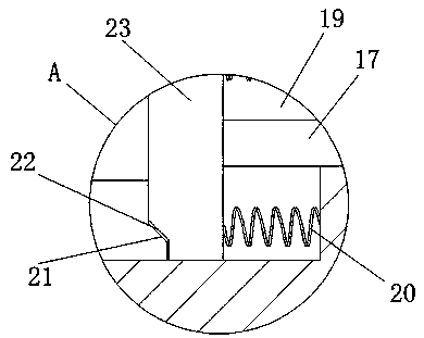
[0021] refer to Figure ...


PUM


Abstract

The invention discloses an injection mold facilitating rapid mold releasing. The mold comprises a base, fixed rods are symmetrically and fixedly connected to the base, the ends, away from the base, ofthe fixed rods are fixedly connected with mounting bases, hydraulic cylinders are mounted on the mounting bases, sliding bases are mounted on the output ends of the hydraulic cylinders, the sliding bases are in sliding connection to the fixed rods, the bottom sides of the sliding bases are fixedly connected with movable molds, a fixed mold base is fixedly connected to the base, two telescopic grooves are symmetrically formed in the fixed mold base, side plates are in sliding connection into the two telescopic grooves, and the two telescopic grooves are internally provided with elastic mechanisms. When push plates are moved upwards, an end face A slowly extrudes an end face B to enable the side plates to move towards the interiors of the telescopic grooves, springs are compressed, a gap isslowly reserved between a product in a mold cavity and the side wall of the mold cavity, during pushing, product resistance is small, and push plate mold releasing is rapier.

Description

technical field [0001] The invention relates to the technical field of injection molds, in particular to an injection mold that is convenient for rapid demoulding. Background technique [0002] The injection mold consists of a moving mold and a fixed mold. The moving mold is installed on the movable template of the injection molding machine, and the fixed mold is installed on the fixed template of the injection molding machine. During injection molding, the movable mold and the fixed mold are closed to form the gating system and the cavity, and the movable mold and the fixed mold are separated to take out the plastic product when the mold is opened. In order to reduce the heavy workload of mold design and manufacturing, most injection molds use standard mold bases. [0003] Generally, after injection molding in the cavity, the injection molding product needs to be cooled and taken out. When taking it out, the ejector pin of the mold is used to cooperate, but some plastic pr...

Claims


Application Information

Patent Timeline
IPC IPC(8): B29C45/26B29C45/40
CPCB29C45/26B29C45/4005
Inventor 不公告发明人
Owner 徐州海之慧生物技术有限公司
Why Eureka
Try Eureka