Magnetic force-based complex mold design and demolding method

A mold design and demoulding technology, which is applied in manufacturing tools, metal processing equipment, processing data acquisition/processing, etc., can solve the problem that the mold is difficult to take out the mold split part, etc., achieve less printing time, easy disassembly and assembly, and low molding cost low effect

Active Publication Date: 2020-06-16
SHANDONG UNIV
View PDF3 Cites 0 Cited by
  • Summary
  • Abstract
  • Description
  • Claims
  • Application Information

AI Technical Summary

Problems solved by technology

[0009] The main purpose of this invention is to solve the problem of difficult removal of complex models or hollow part model molds and the connection problem of mold split parts, and meet the design requirements for complex models to be manufactured using the method of mold opening

Method used


Image

  • Magnetic force-based complex mold design and demolding method
  • Magnetic force-based complex mold design and demolding method
  • Magnetic force-based complex mold design and demolding method

Examples


Embodiment 1

[0037] The present invention will be further described below in conjunction with the accompanying drawings and embodiments.

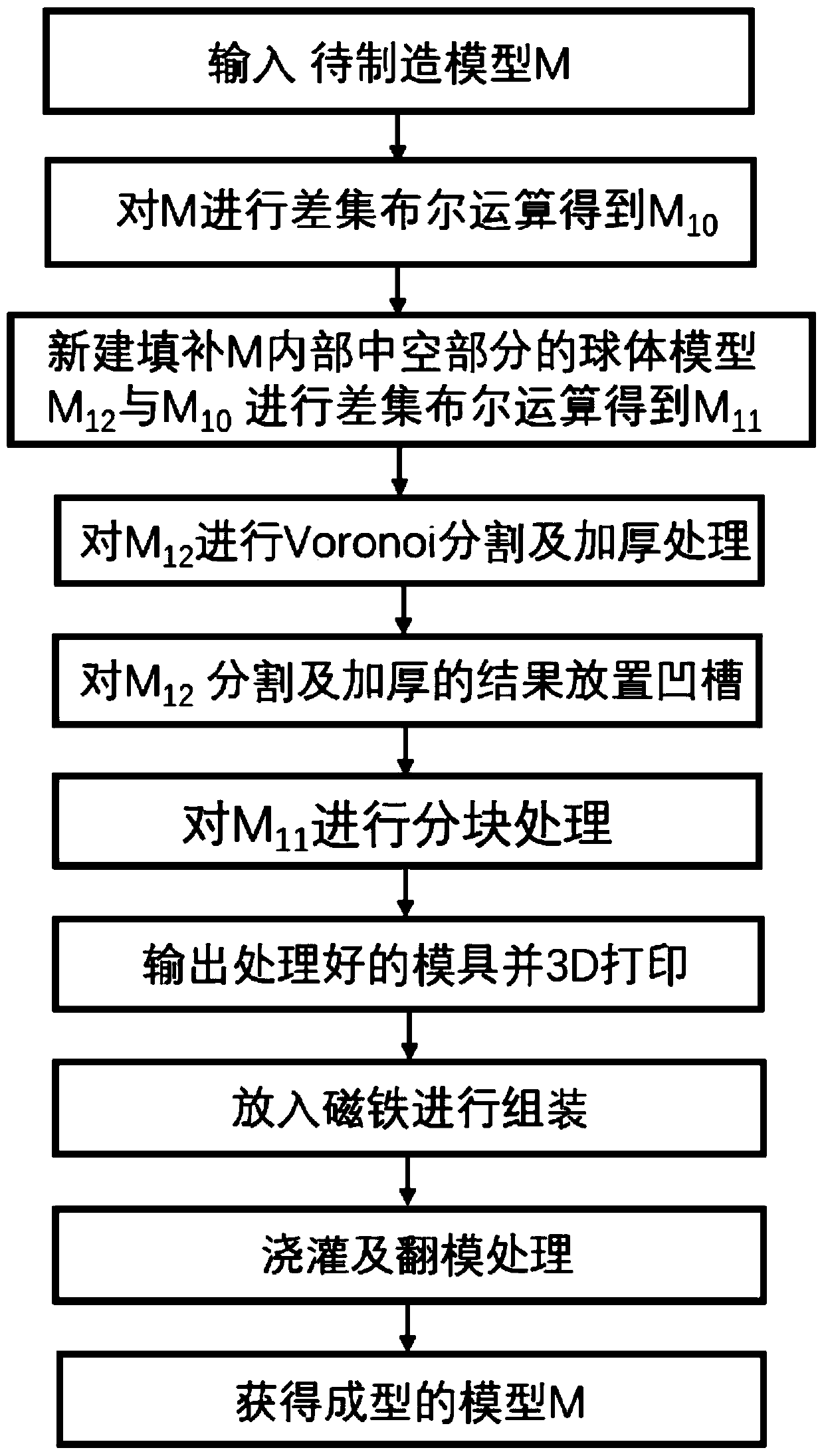
[0038] figure 1 It is a flow chart of a complex mold design and demoulding method based on magnetic force of the present invention.

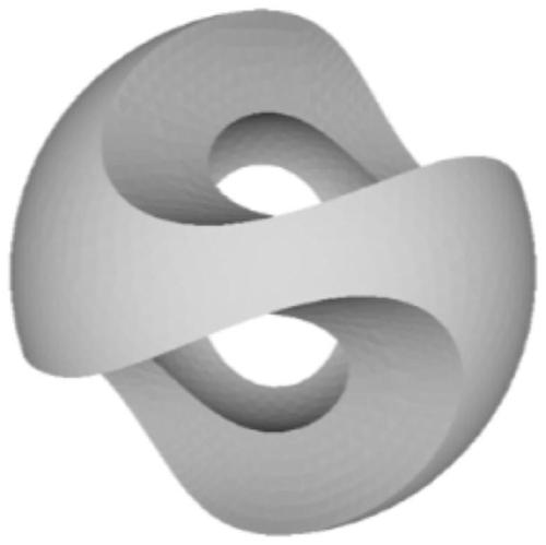
[0039] In this embodiment, M is used to represent the input model to be manufactured, as shown in the attached figure 2 shown.

[0040] Such as figure 1 Shown, a kind of complex mold design and demoulding method based on magnetic force of the present invention comprises:

[0041] Step (1): Input the model M to be manufactured, and obtain the initial mold M10 to be divided after the Boolean difference operation.

[0042] Among them, before performing Boolean operation processing on the input model M, it also includes:

[0043] Subdivide or simplify the grid input to the model M to a certain extent to avoid Boolean operation errors due to the grid being too sparse or too dense.

[0044] Among them, the specific proce...

Embodiment 2

[0076] A complex mold design and demoulding method based on magnetic force, comprising the following steps:

[0077] Input the model to be manufactured, and obtain the initial model after the difference operation; create the internal model of the model to be manufactured; obtain the external model after the difference operation between the initial model and the internal model;

[0078] Divide the internal model to form mold modules that can be taken out; grooves are provided on the splicing surface of each mold module, and magnets are placed in the grooves;

[0079] Divide the external model, and dig holes to get the material pouring port;

[0080] Set up the mold body, put magnets in the groove position for assembly, pour through the pouring port after assembly, and demould after cooling and solidification.

[0081] The specific steps of obtaining the initial model include: creating a simple model that can surround the model according to the model to be manufactured, using t...


PUM


Abstract

The invention provides a magnetic force-based complex mold design and demolding method. The method comprises the following steps of inputting a to-be-manufactured model, and performing difference setoperation to obtain an initial model; creating an internal model of the to-be-manufactured model; performing difference set operation on the initial model and the internal model to obtain an externalmodel; performing segmentation on the internal model to form mold modules which can be taken out; forming a groove in a splicing surface of each mold module, wherein the grooves are used for containing magnets; performing segmentation on the external model, and meanwhile, digging holes to obtain material pouring ports; and setting mold entities, putting the magnets in the grooves for assembly, performing pouring through the pouring ports after assembly, and performing demolding after cooling and solidification. By adopting a mode of splicing after segmentation, disassembly and assembly are facilitated and the design is flexible and variable.

Description

technical field [0001] The invention relates to the field of model mold design and demoulding, in particular to a method for mold division and demoulding of complex models or hollow models. Background technique [0002] A mold is a tool used to make shaped objects. This tool is composed of various parts, and different molds are composed of different parts. It mainly realizes the processing of the shape of the article through the change of the physical state of the formed material. Because the mold has the advantages of high production efficiency, good quality, low cost, saving energy and raw materials, it is already a basic process equipment in industrial production, a high-value-added high-precision integrated product, and a high-tech industrialization. In important areas, the level of technology has become an important symbol to measure the level of a country's manufacturing industry. [0003] 3D printing, also known as additive manufacturing, refers to the process of la...

Claims


Application Information

Patent Timeline
Patent Type & Authority Applications(China)
IPC IPC(8): B29C64/386B29C64/379B33Y50/00B33Y40/20
CPCB33Y40/00B33Y50/00B29C64/379B29C64/386
Inventor 吕琳孙玉璐刘培庆
Owner SHANDONG UNIV
Why Eureka
Try Eureka