Concrete screw-conveying equipment

A technology of screw conveying and concrete, applied in the direction of conveyor, transportation and packaging, packaging, etc., can solve the problem of inconvenient operator maintenance of conveyor, achieve the effect of convenient cleaning and maintenance, and improve sealing

Active Publication Date: 2020-06-16
HANGZHOU MINGYUN CONCRETE
View PDF10 Cites 0 Cited by
  • Summary
  • Abstract
  • Description
  • Claims
  • Application Information

AI Technical Summary

Problems solved by technology

[0003] In the concrete preparation process, the raw materials need to be transported by the screw conveyor. After the screw conveyor is used for one end, once the internal structure of the conveyor is damaged, the operator needs to disassemble the conveyor for maintenance. The existing conveyor Usually a whole piece, it is inconvenient for the operator to overhaul the interior of the conveyor

Method used


Image

  • Concrete screw-conveying equipment
  • Concrete screw-conveying equipment

Examples


Embodiment Construction

[0026] The present invention will be described in further detail below in conjunction with the accompanying drawings.

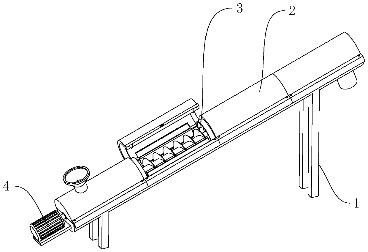
[0027] Such as figure 1 As shown, it is a kind of concrete screw conveying equipment disclosed by the present invention, which includes a support 1, a delivery pipe 2 is fixedly connected to the support 1, and an auger 3 is rotatably connected between the inner walls of the two ends of the delivery pipe 2. One end is fixedly connected with a drive motor 4 for driving the auger 3 to rotate.

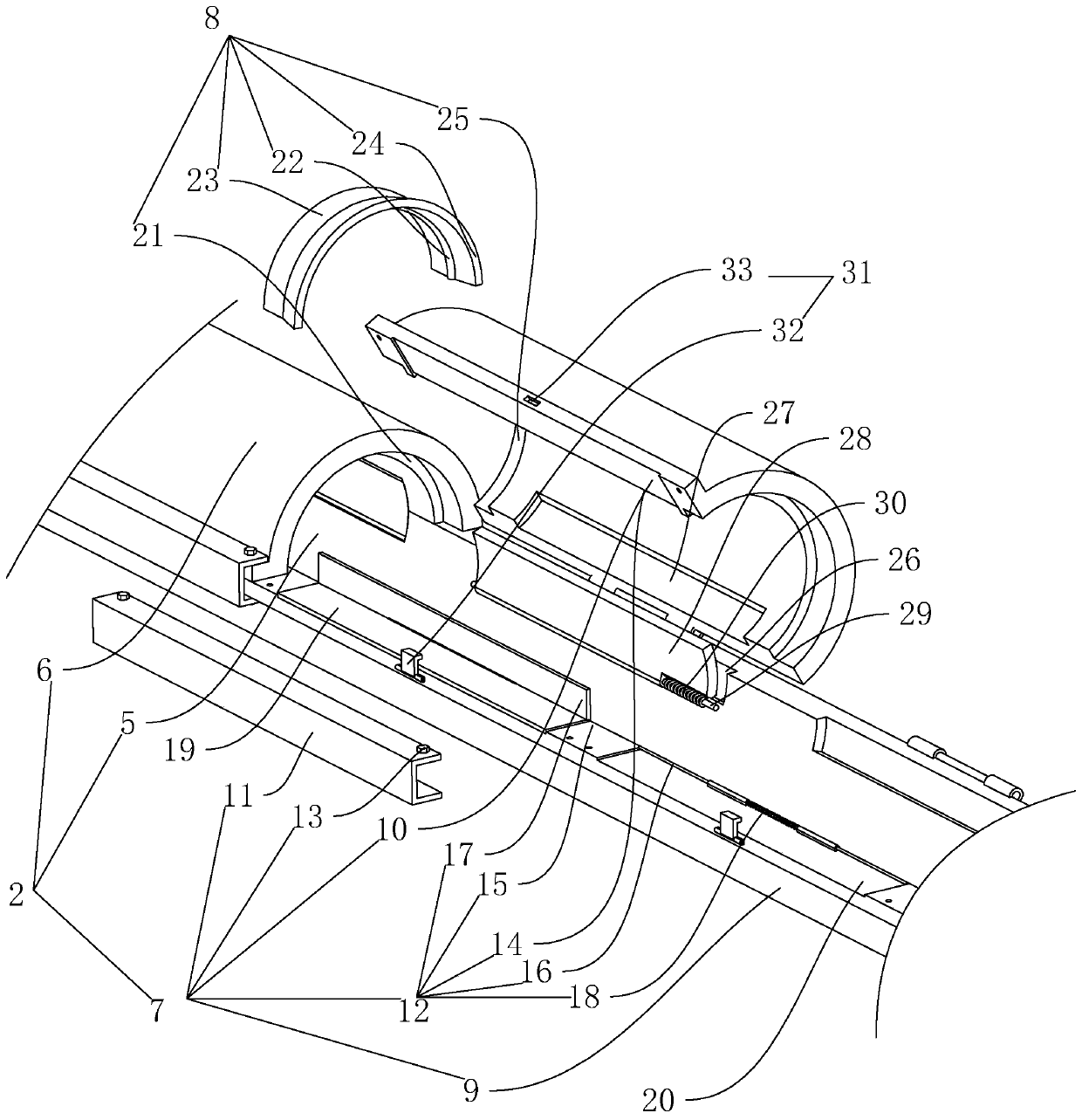
[0028] Such as figure 2 As shown, the delivery tube 2 includes a first semicircular tube 5, a second semicircular tube 6 and a locking mechanism 7, the first semicircular tube 5 is fixedly connected to the support 1, and one side of the second semicircular tube 6 is connected to the first semicircular tube 5. Rotation connection between the sides, the inner wall of the first semicircular tube 5 and the inner wall of the second semicircular tube 6 are spliced ​​into a c...


PUM


Abstract

The invention relates to concrete screw-conveying equipment which comprises a support. A conveying pipe is fixedly connected onto the support; a packing auger is rotatably connected onto the inner walls of two ends of the conveying pipe; a drive motor for driving the packing auger to rotate is fixedly connected onto one end of the conveying pipe; the conveying pipe comprises a first semicircular pipe fixedly connected onto the support, a plurality of groups of second semicircular pipe pipes rotatably connected onto one side of the first semicircular pipe, and locking mechanisms arranged between the first semicircular pipe and the second semicircular pipes; a sealing mechanism is arranged between each two groups of adjacent second semicircular pipes; when the inner wall of the conveying pipe needs to be cleaned and maintained, an operator opens the second semicircular pipes and covers the first semicircular pipe after repairing, the second semicircular pipes are locked onto the first semicircular pipe through the locking mechanisms, and the sealability between each two groups of adjacent second semicircular pipes is ensured through the corresponding sealing mechanism, so that the operator can conveniently clean and maintain the inner part of the conveying pipe.

Description

technical field [0001] The invention relates to a conveying device, in particular to a concrete screw conveying device. Background technique [0002] Screw conveyors can be divided into shaft screw conveyors and shaftless screw conveyors in terms of conveying form, and can be divided into U-shaped screw conveyors and tubular screw conveyors in terms of appearance. Shafted screw conveyors are suitable for non-viscous dry powder materials and small particle materials (such as: cement, fly ash, lime, grain, etc.), while shaftless screw conveyors are suitable for conveying viscous and easily entangled materials. (Example: sludge, biomass, garbage, etc.) The working principle of the screw conveyor is that the rotating screw blades push the material to be transported by the screw conveyor, so that the force that prevents the material from rotating with the screw conveyor blade is the weight of the material itself and The frictional resistance of the screw conveyor casing to the m...

Claims


Application Information

Patent Timeline
IPC IPC(8): B65G33/14B65G33/24
CPCB65G33/14B65G33/24B65G2201/04
Inventor 吴天森张闯张伟
Owner HANGZHOU MINGYUN CONCRETE
Why Eureka
Try Eureka