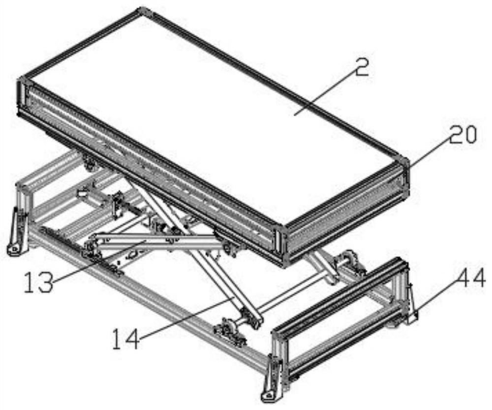
[0004] The purpose of the present invention is to provide a bridge structure for relining manipulators to solve the following technical problems: (1) The first connecting plate is driven up and down by the first cylinder
piston rod through the thrust seat, and the first connecting plate drives the second connecting plate up and down. The two second connecting plates at the bottom drive the two fixing bars up and down, and at the same time, the
piston rod of the second cylinder on the support frame drives the
pallet up and down to complete the height adjustment of the pallet. Take it off, put the liner between the two partition bars on the pallet, and through the setting of the first cylinder and the second cylinder, the pallet on the lining trolley can complete two-stage lifting, which can satisfy people of different heights. The lining plate is placed on the supporting plate of the lining trolley, which has strong practicability. At the same time, when the structure is installed in the ball mill where the lining trolley enters, the height of the supporting plate can be reduced to meet the entry of different ball mill calibers, and solve the problem of different heights in the prior art. It is difficult for the operator to place the liner on the liner trolley. At the same time, when the
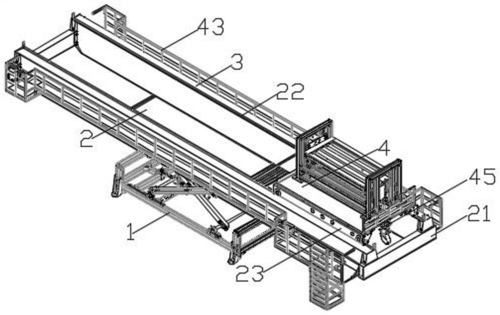
caliber of the ball mill is small, the height of the liner trolley cannot meet the technical problems of entering the ball mill; (2) By pushing the bottom frame to the opening of the ball mill through the casters at the bottom, the first The output shaft of the motor drives the screw to rotate, and the screw cooperates with the screw block to drive the first sliding link blocks on both sides to slide on the first slide rail through the first connecting shaft, and the first connecting shaft cooperates with the first jacking channel to rotate , the first lifting channel steel rotates with the second lifting channel steel, the two sides of the second lifting channel steel cooperate with the second connecting shaft and the third connecting shaft to rotate respectively, and the top of the first lifting channel steel cooperates with the third connecting shaft to drive The second sliding link blocks on both sides slide on the second slide rail, and then drive the support plate up and down through the connecting frame, lift the two bridges to the opening position of the ball mill, push the bridge into the opening of the ball mill through the casters at the bottom of the
chassis, Through the design of the first lifting channel steel and the second lifting channel steel, the lifting work of the bridge frame can be completed, so that the operator can go on the bridge frame conveniently. At the same time, through this design, it can meet the entry of ball mills at different heights, with high applicability. Solve the technical problems in the prior art that the height of the ball mill is different, the height of the lining trolley is difficult to adjust into the ball mill, and it is difficult for the operator to
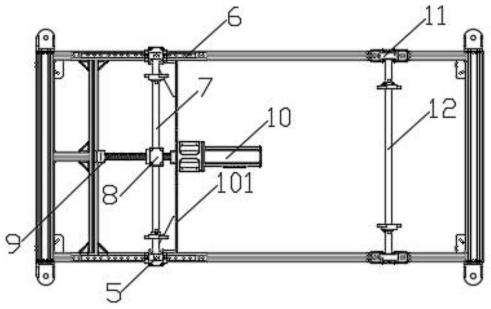
mount the bridge; (3) The output shaft of the second motor drives the
pulley to rotate, and then the lining trolley passes through the installation bars on both sides The four pulleys slide on the guide rails on the bridge frame to move the lining trolley to the liner replacement position. Through this design, the lining trolley can move freely on the bridge frame, which is convenient for the lining trolley to move to the proper liner replacement position in the ball mill. Further, it facilitates the replacement of the lining board, and solves the technical problem that the lining trolley in the prior art is inconvenient to move in the ball mill, and thus the replacement of the lining board is inconvenient

