Underground oil-water separator

An oil-water separator and oil-water separation technology, which is applied in wellbore/well parts, production fluid, earthwork drilling and production, etc., can solve the problems of long mechanical parts and high maintenance costs, and achieve reduced oil production frequency, no energy consumption, and simple structure Effect

Pending Publication Date: 2020-06-16
张莅莱
View PDF0 Cites 0 Cited by
  • Summary
  • Abstract
  • Description
  • Claims
  • Application Information

AI Technical Summary

Problems solved by technology

Because the oil well is relatively deep and the mechanical parts are long, after a failure occurs, the equipment needs to be taken from the underground to the ground, and the maintenance cost is high

Method used


Image

  • Underground oil-water separator
  • Underground oil-water separator
  • Underground oil-water separator

Examples


Embodiment Construction

[0013] The downhole oil-water separator provided by the present invention will be further explained in conjunction with the accompanying drawings and the existing oil production technology.

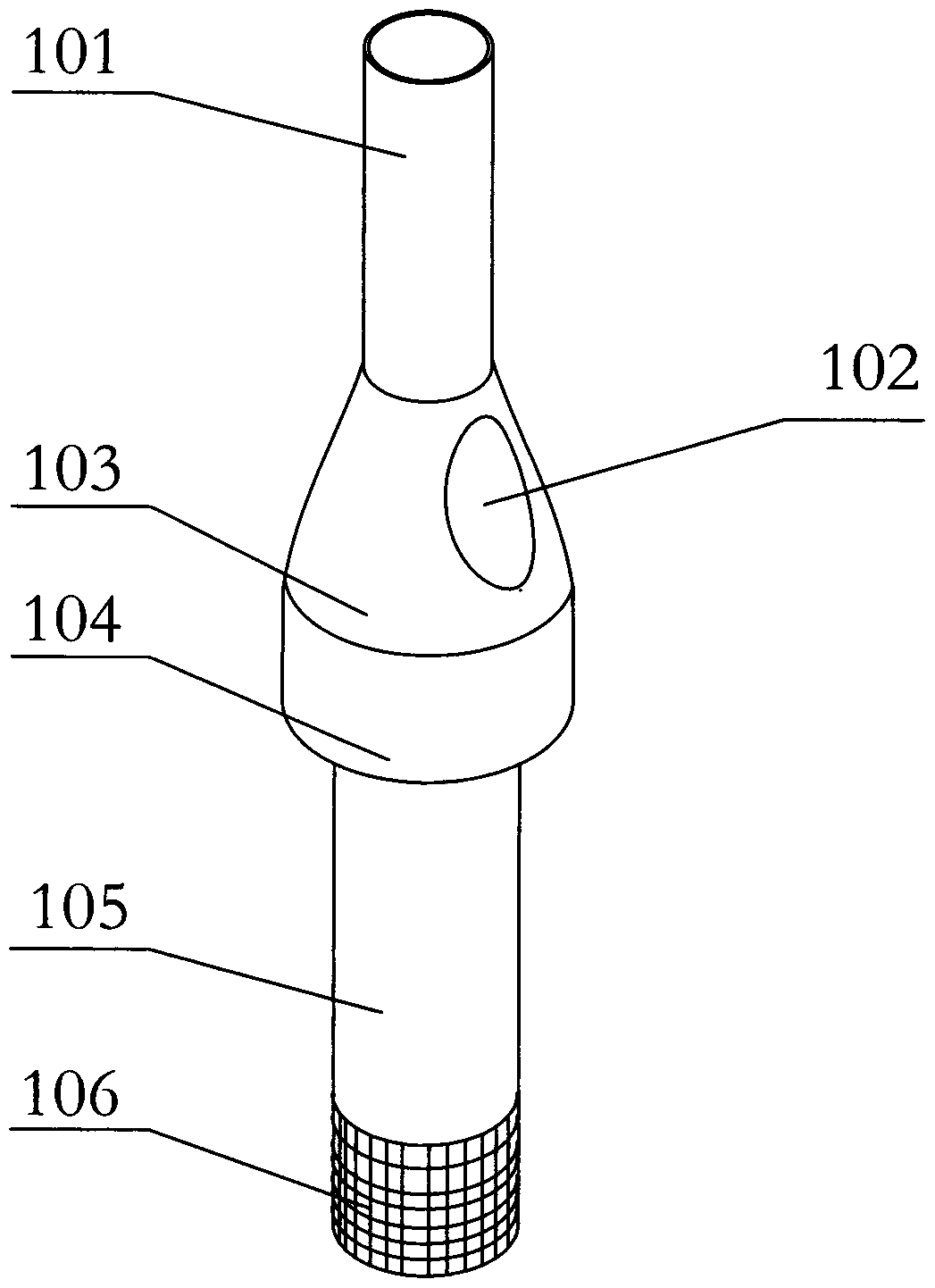
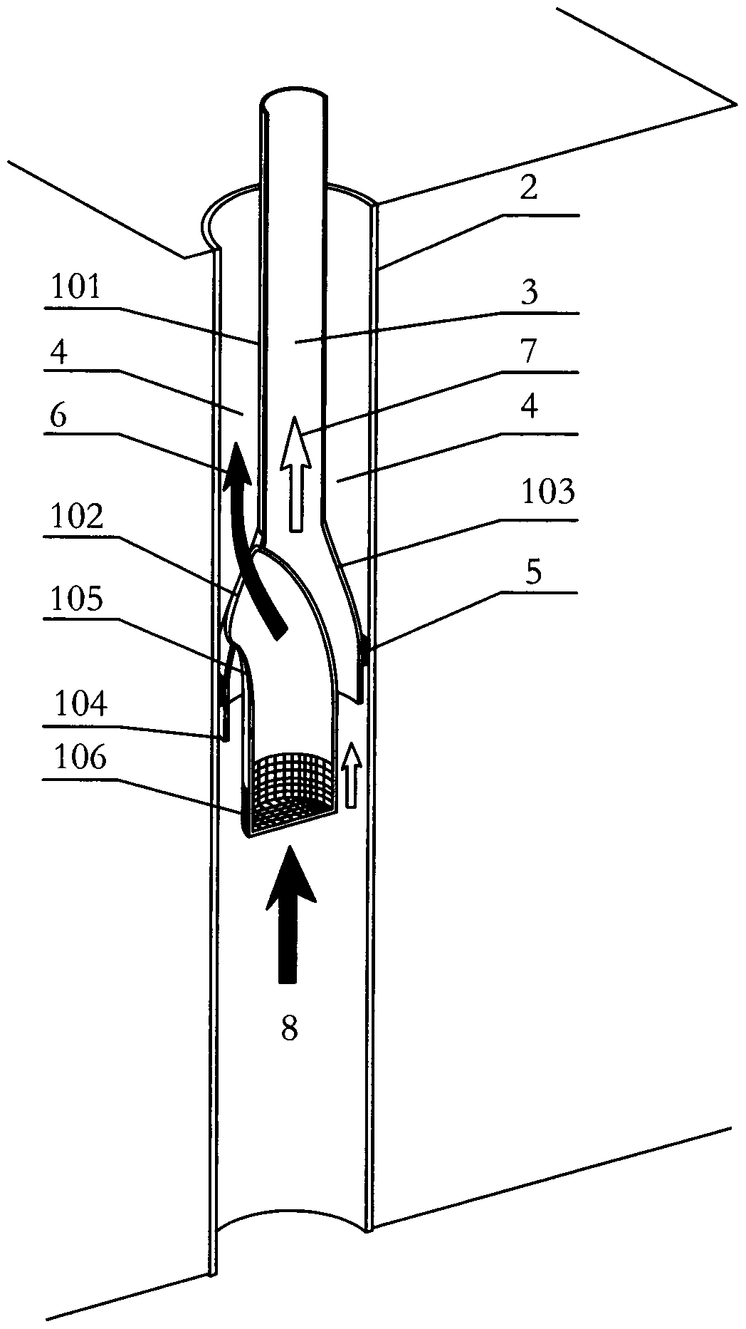
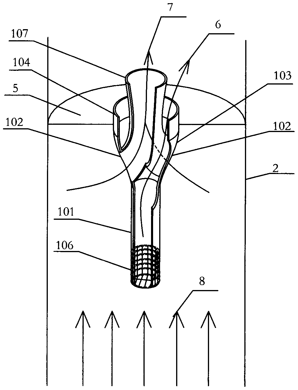
[0014] Such as figure 1 , figure 2 A downhole oil-water separator shown includes: a conical surface (103), a J-shaped elbow (105); the upper end of the conical surface (103) is connected with a small opening (101), and its lower end is connected with a large opening (104); The conical surface (103) is also provided with a round hole (102); the J-shaped elbow (105) is inverted, the upper end is connected to the round hole (102), and the oil-water separation membrane (106) is connected to the lower end.

[0015] The oil-water separation membrane (106) can be a net coated with an oleophobic material on the outer surface, or it can be other new invention materials; the waste water can pass through smoothly, and the crude oil agglomerate is due to the repulsion between the molecules of the c...


PUM


Abstract

The invention discloses an underground oil-water separator. The underground oil-water separator comprises a conical surface and a J-shaped bent pipe. The upper end of the conical surface is connectedwith a small opening, and the lower end of the conical surface is connected with a large opening. A round hole is further formed in the conical surface. The J-shaped bent pipe is inversely arranged. The upper end of the J-shaped bent pipe is connected with the round hole, and the lower end of the J-shaped bent pipe is connected with an oil-water separating membrane. According to the underground oil-water separator disclosed in the invention, the outer side of the large opening is sleeved with a packer, the packer is contracted after being placed at the proper position inside an oil well, the large opening is made to be tightly attached to the inner wall of the oil well, and crude oil separated out of well fluid is gradually gathered into the small opening in the ascending process under thecollection effect of a funnel; and water passes through the oil-water separating membrane and arrives at the outer side of the small opening along an inner cavity of the J-shaped bent pipe, and therefore oil-water separation is realized. The underground oil-water separator has the beneficial effects that underground oil and water are separated with the physics principle, the structure is simple and installation and maintenance cost is low.

Description

technical field [0001] The invention relates to an auxiliary tool for oil-water separation in the process of oil production, in particular to an oil-water separation device in a downhole. Background technique [0002] A large proportion of domestic oil wells are low-yield oil wells, and their water content generally reaches more than 70%, and the water content is directly related to the cost of oil production. At present, a domestic oil company is doing downhole oil-water separation experiments to realize the new technology of "downhole oil-water separation, production and injection in the same well". But the downhole oil-water separation that it adopts is to utilize the motor on the ground to drive the downhole separation pump to realize. Because the oil well is relatively deep and the mechanical parts are long, after a failure occurs, the equipment needs to be taken from the underground to the surface, and the maintenance cost is high. In view of this, it is particularly...

Claims


Application Information

Patent Timeline
Patent Type & Authority Applications(China)
IPC IPC(8): E21B43/38E21B43/40
CPCE21B43/38E21B43/385
Inventor 张莅莱
Owner 张莅莱
Why Eureka
Try Eureka