a clutch assembly

A clutch and clutch plate technology, applied in the field of clutches, can solve the problems of increasing clutch plate ablation, reducing clutch plate friction, shortening clutch service life, etc., to achieve the effects of increasing air exchange efficiency, reducing severe wear, and increasing friction

Active Publication Date: 2021-07-20
绍兴铭盾工具有限公司
View PDF11 Cites 0 Cited by
  • Summary
  • Abstract
  • Description
  • Claims
  • Application Information

AI Technical Summary

Problems solved by technology

One side of the thrust limiting helical cam is fixed to the bottom plate of the assembly, the other end is provided with a cam, and a spring is installed between the inner spline plate and the thrust limiting helical cam on the guide column; The existing technology reduces the axial pressure, so that the mechanical conversion of driving and climbing is stable, and the clutch plate is subject to greater wear when it rotates. Due to climbing or when a large torque is required, or when the speed needs to be controlled for a long period of semi-linkage, the clutch surface A large amount of heat is generated due to sliding. If the heat is not removed in time, the friction force of the clutch plate will be seriously reduced. At the same time, the high temperature will increase the ablation of the clutch plate and seriously shorten the service life of the clutch.

Method used


Image

  • a clutch assembly
  • a clutch assembly
  • a clutch assembly

Examples


Embodiment approach

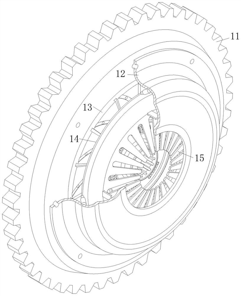
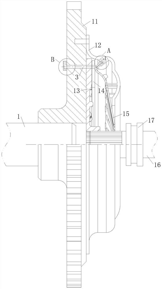
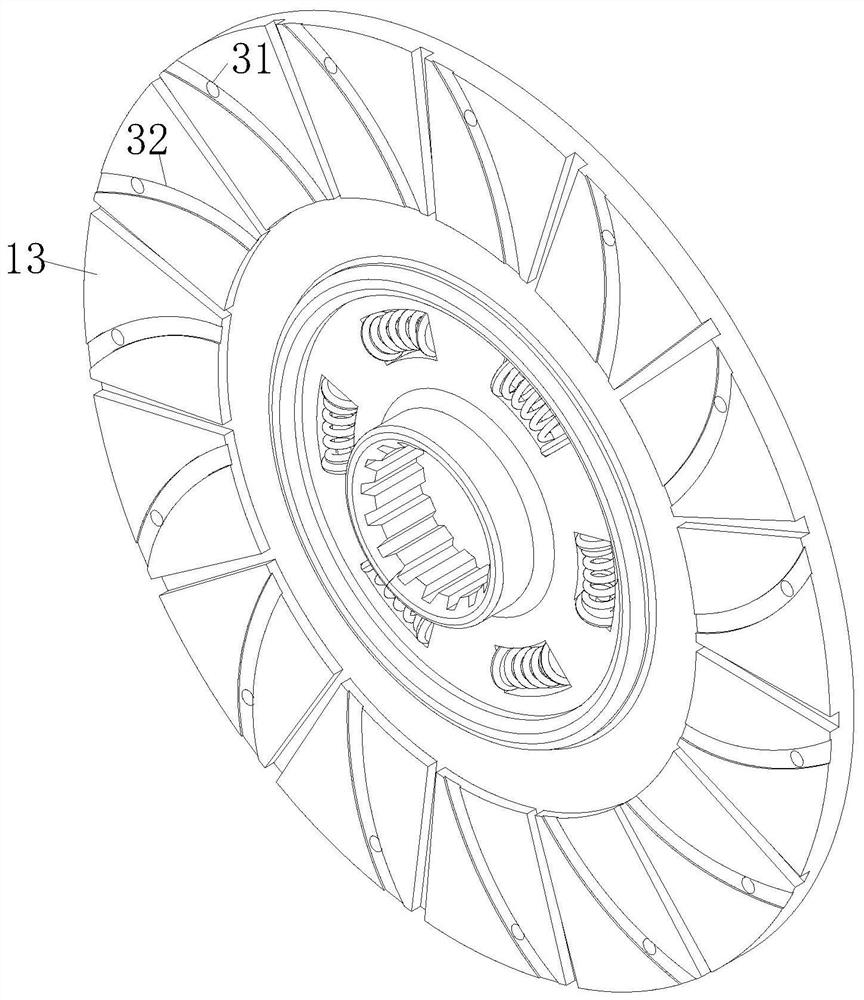
[0025] As an embodiment of the present invention, a set of No. 4 holes 3 for ventilation is provided on the flywheel 11; No. 5 holes 31 are provided on the clutch plate 13 corresponding to the No. 4 holes 3, through which air flows through No. 5 hole 31 and No. 4 hole 3 further increase the heat dissipation efficiency of clutch disc 13; through No. 4 hole 3 and No. 5 hole 31, the air ejected from No. 1 hole 22 is increased to enter the center of the contact part between clutch disc 13 and flywheel 11. Efficiency, so that the clutch plate 13 receives cooling airflow in multiple directions, increases the heat transfer efficiency between the clutch plate 13 and the airflow, further increases the heat dissipation speed of the clutch plate 13, reduces the ablation of the clutch plate 13 caused by high temperature, and then causes the torque of the clutch The transmission efficiency is reduced, and at the same time, the life of the clutch plate 13 is reduced.

[0026] As an embodime...


PUM


Abstract

The invention belongs to the technical field of clutches, specifically a clutch assembly, including a drive shaft; a flywheel is fixedly connected to one end of the drive shaft, and a clutch cover is fixedly connected to the end of the flywheel away from the drive shaft; the cavity between the clutch cover and the flywheel There are clutch plate, pressure plate and diaphragm spring in sequence; there is a slide hole in the clutch cover, the axis of the slide hole and the cross section of the inner wall of the clutch cover form an included angle of 45°, and a sliding column is slidably connected to the sliding hole, and the inside of the sliding column slides along the There is a No. 1 hole in the axial direction of the column, and a No. 2 hole connected to the No. 1 hole is opened at the bottom of the No. 1 hole along the diameter direction of the sliding column section; an air storage chamber is opened in the clutch cover on one side of the sliding hole, and the air storage room passes through the pipe and The one-way valve communicates with the bottom of the sliding hole; the air storage chamber communicates with the middle of the sliding hole through the No. 3 hole; the present invention uses the spool to squeeze the sliding hole under the action of centrifugal force to generate compressed gas and spray it to the clutch plate to reduce the temperature of the clutch plate , Increase the transmission efficiency of the clutch plate and the flywheel.

Description

technical field [0001] The invention belongs to the technical field of clutches, in particular to a clutch assembly. Background technique [0002] The clutch is located in the flywheel housing between the engine and the gearbox, and the clutch assembly is fixed on the rear plane of the flywheel with screws, and the output shaft of the clutch is the input shaft of the gearbox. During the driving process of the car, the driver can step on or release the clutch pedal as needed to temporarily separate and gradually engage the engine and the gearbox, so as to cut off or transmit the power input from the engine to the transmission. Clutches are common components in mechanical transmissions that can disengage or engage the transmission system at any time. The basic requirements are: smooth joint, rapid and thorough separation; convenient adjustment and repair; small external size; small mass; good wear resistance and sufficient heat dissipation capacity; Two types of friction. ...

Claims


Application Information

Patent Timeline
Patent Type & Authority Patents(China)
IPC IPC(8): F16D25/04F16D25/12
CPCF16D25/04F16D25/12
Inventor 孙亮张翔
Owner 绍兴铭盾工具有限公司
Why Eureka
Try Eureka