
A detection device for determining the location of reservoir seepage and its application method

A detection device and reservoir technology, applied in the detection field, can solve the problems of waste, poor precision, inconvenient use, etc., and achieve the effects of simple operation, flexible detection size, and easy portability

Active Publication Date: 2022-01-25
STATE GRID CORP OF CHINA +2
View PDF0 Cites 0 Cited by
  • Summary
  • Abstract
  • Description
  • Claims
  • Application Information

AI Technical Summary

Problems solved by technology

These technologies have certain effects in delineating a large-scale seepage area, but there are obvious shortcomings: (1) drilling and ship surveying are required, which consumes a lot of financial resources; (2) more personnel cooperation is required, and more waste is required (3) It needs regular monitoring, which takes up a lot of time; (4) It needs to use a variety of instruments and equipment, which is inconvenient to use; (5) It needs to test multiple items and model analysis, and the data processing is cumbersome; (6) ) can only give a large-scale leakage range in the end, and the accuracy is poor

Method used


Image

  • A detection device for determining the location of reservoir seepage and its application method
  • A detection device for determining the location of reservoir seepage and its application method
  • A detection device for determining the location of reservoir seepage and its application method

Examples


Embodiment 1

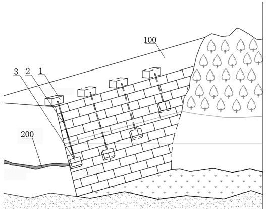
[0048] see Figure 1 to Figure 5 , the present invention provides a detection device for determining the leakage position of a reservoir, comprising a control device 1, the control device 1 is connected to a water body airtight tank 3 through a connecting piece 2;

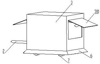
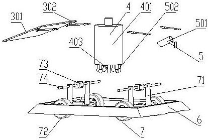
[0049] The water body airtight box 3 comprises the box body of bottom opening, and the box body of water body airtight box 3 is provided with the box door 301 that can open, and water body airtight box 3 interior is provided with the delivery mechanism 4 that is used for injecting tracer, and is used for observing indication. Observation agencies for tracers5;

[0050] Along the edge of the bottom opening of the water body airtight box 3, a seal 6 that can block the water body from entering the inside of the water body airtight box 3 is provided;

[0051] The control device 1 includes a main control module that forms a control loop and a data feedback path with each component of the water body airtight tank 3 , an...

Embodiment 2

[0075] On the basis of embodiment 1, the using method of this detection device is:

[0076] S1. Detect each component of the device, keep the device in the initial state, ensure that the chamber door 301 is closed, and the tracer inside the storage box 402 is filled in place;

[0077] S2. Transport the device to the reservoir dam 100 to be inspected, ensure that the mobile assembly 7 is in an unfolded state, and open the box door 301. The water body airtight box 3 is moved down along the surface of the dam to the liquid level of the reservoir through the mobile assembly 7. During this process Ensure that the connecting piece 2 is firmly connected to the water body airtight box 3 and the control device 1;

[0078] S3. After the water body airtight box 3 moves to the first observation area, the control device 1 controls the door 301 to close, and the moving assembly 7 becomes the storage state. At this time, the wheels 72 are retracted, and the water body airtight box 3 is under...

Embodiment 3

[0084] On the basis of Embodiment 1, the movement of the water body airtight box 3 can be realized by changing the length of the connecting piece 6, and relying on the self-weight of the device to move down the embankment slope.

[0085] Or add power to the wheel 72 on the moving assembly 7, such as a motor, and drive the wheel 72 to rotate through the motor.


PUM


Abstract

The invention discloses a detection device for determining the leakage position of a reservoir and a method for using the same, and relates to the field of detection equipment. An open box body, an openable box door is arranged on the box body of the water body airtight box, and a release mechanism for placing tracers and an observation mechanism for observing the tracer are arranged inside the water body airtight box; along the water body airtight box The bottom opening edge of the water body is provided with a seal that can block the water body from entering the inside of the water body airtight box. The beneficial effect of the invention is that it can seal the water body within a certain range, keep the tracer diffusion free from external influences such as fish swimming, wind blowing, etc., so that it is convenient to accurately determine whether the detection area is leaking and the leaking position. The tracer concentration sensor and high-precision camera system can accurately record the diffusion paths of the color tracer and the colorless tracer to achieve mutual verification.

Description

technical field [0001] The invention relates to the technical field of detection, in particular to a detection device for determining the leakage position of a reservoir and an application method thereof. Background technique [0002] Almost all reservoirs in the world have leakage problems to varying degrees. Leakage has buried a serious safety hazard for the normal operation of the reservoir. In order to determine the location of reservoir seepage, a variety of detection techniques have emerged. Currently popular technologies include (1) drilling monitoring on the dam crest in potential leakage areas, including temperature, water chemistry, flow velocity and flow direction; (2) putting liquid tracers in front of reservoirs in potential leakage areas, including adding salt or fluorescent powder , Connectivity test. These technologies have certain effects in delineating a large-scale seepage area, but there are obvious shortcomings: (1) drilling and ship surveying are req...

Claims


Application Information

Patent Timeline
Patent Type & Authority Patents(China)
IPC IPC(8): G01M3/20G01N15/08
CPCG01M3/20G01N15/0806G01N15/082
Inventor 张立张玉平
Owner STATE GRID CORP OF CHINA
Features
  • Generate Ideas
  • Intellectual Property
  • Life Sciences
  • Materials
  • Tech Scout
  • Unparalleled Data Quality
  • Higher Quality Content
  • 60% Fewer Hallucinations
Learn More