Vacuum cleaner with power control in dependence on mode of operation of electrical brush

A technology for vacuum cleaners and control units, which is applied in the installation of vacuum cleaners, vacuum cleaner equipment, and electrical equipment, and can solve problems such as the complex speed of control units

Inactive Publication Date: 2003-07-02
KONINKLIJKE PHILIPS ELECTRONICS NV
View PDF5 Cites 1 Cited by
  • Summary
  • Abstract
  • Description
  • Claims
  • Application Information

AI Technical Summary

Problems solved by technology

However, this results in a more

Method used


Image

  • Vacuum cleaner with power control in dependence on mode of operation of electrical brush
  • Vacuum cleaner with power control in dependence on mode of operation of electrical brush
  • Vacuum cleaner with power control in dependence on mode of operation of electrical brush

Examples


Embodiment Construction

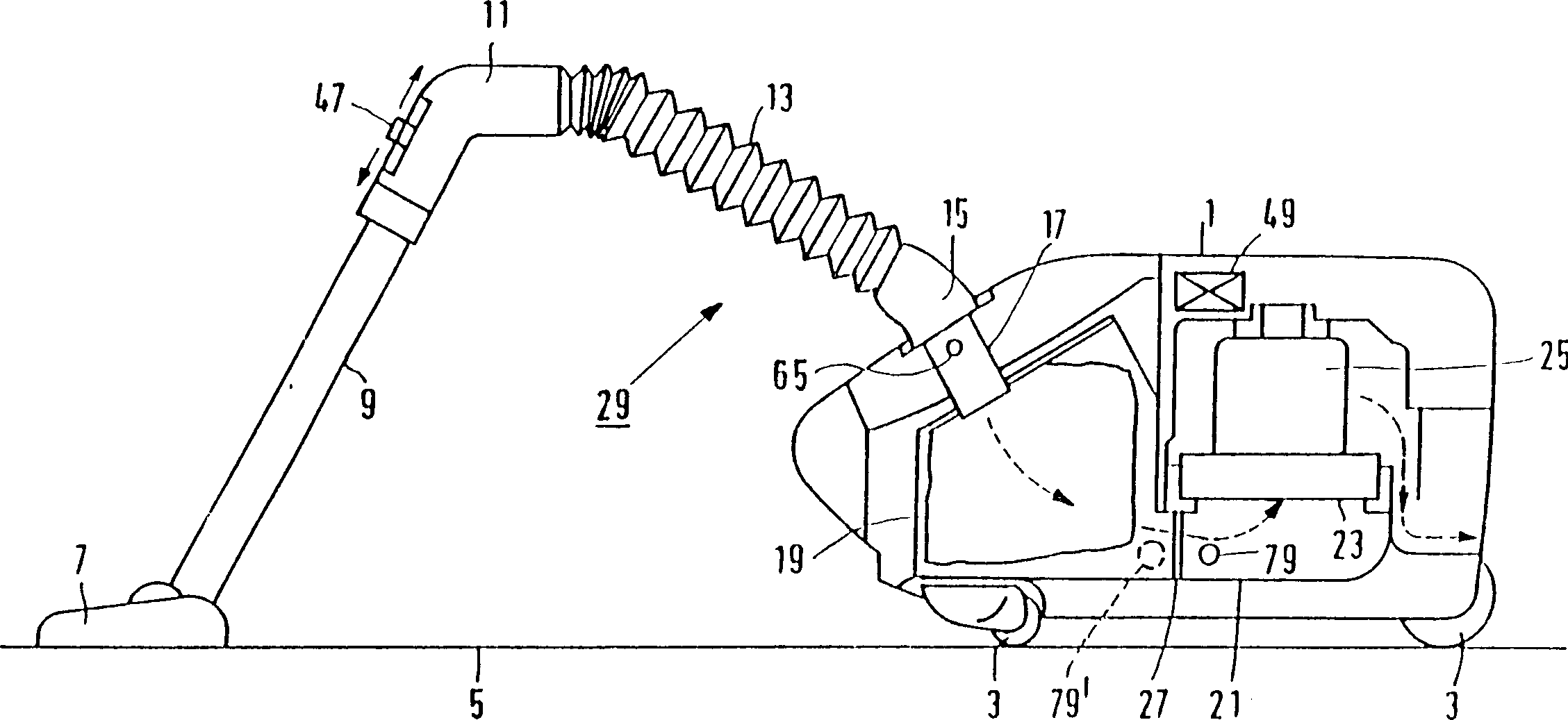
[0020] figure 1 The vacuum cleaner according to the invention shown comprises a housing 1 with a number of wheels 3, by means of which the housing 1 can be moved on the surface 5 to be cleaned. The vacuum cleaner also includes a suction member 7 which is rotatably connected with the suction pipe 9. The suction tube 9 is connected to the handle 11, and the handle 11 is connected to the housing 1 through a suction hose 13 and a connecting piece 15. The duct 17 in the housing 1 ends with a replaceable dust collector 19. Another duct 21 in the housing 1 connects the dust collector 19 with the suction unit 23, and the suction unit 23 can be driven by the first motor 25 in the housing 1. The filter 27 is on the other duct 21. During operation, the suction unit 23 generates a partial vacuum in the air path 29 composed of the suction member 7, the suction tube 9, the suction hose 13, the duct 17, the dust collector 19 and the other duct 21. An air flow is generated in the path 29, and du...


PUM


Abstract

A vacuum cleaner comprises a suction unit (23) which is drivable by means of a first electric motor (25). A suction attachment (7) of the vacuum cleaner comprises a rotatable brush (41) which is drivable by means of a second electric motor. The vacuum cleaner comprises a control unit (29) by means of which an electric current through the first motor (25) can be controlled. In accordance with the invention the control unit (29) controls the current through the first motor (25) as a function of a mode of operation of the brush (41), which mode can be selected by a user of the vacuum cleaner. In this way, the suction power of the suction unit (23) is adapted to the mode of operation of the brush (41), thereby improving a relationship between cleaning performance, ease of use, current consumption and noise production of the vacuum cleaner. In a special embodiment of a vacuum cleaner in accordance with the invention, the control unit (29) controls an air pressure and an air flow in the suction attachment (7) in such a manner that the air pressure does not decrease below a first limit value (HMIN), the air flow does not exceed a second limit value (QMAX), and at least one of the limit values (HMIN, QMAX) is substantially reached.

Description

Technical field [0001] The present invention relates to a vacuum cleaner. The vacuum cleaner includes a housing, a suction unit that is installed in the housing and can be driven by a first motor, a suction member having a rotating brush that can be driven by a second motor, and a suction unit for controlling the flow through the first motor. Electronic control unit for motor current. Background technique [0002] From EP-B-0458057, the vacuum cleaner defined in the opening paragraph can be known. There is a pressure sensor in the suction part of the vacuum cleaner to measure the air pressure. During the working process, the user of the vacuum cleaner moves the vacuum cleaner on the surface to be cleaned. Due to the unevenness of the surface, the resistance encountered by the gas sucked in from the surface and the suction member by the suction unit fluctuates. Therefore, the air pressure in the suction member also fluctuates. The amplitude of air pressure fluctuations in the suct...

Claims


Application Information

Patent Timeline
IPC IPC(8): A47L9/28
CPCA47L9/2894A47L9/2857Y02B40/82A47L9/2847A47L9/2821Y02B40/00A47L9/28
Inventor J·A·T·德利森M·A·A·沙力格R·A·维萨
Owner KONINKLIJKE PHILIPS ELECTRONICS NV
Why Eureka
Try Eureka