
Light distribution structure and element, related method and uses

A technology of light distribution and structure, applied in optical components, light guides, optics, etc., can solve problems such as low efficiency

Active Publication Date: 2020-06-16
NITTO DENKO CORP
View PDF12 Cites 1 Cited by
  • Summary
  • Abstract
  • Description
  • Claims
  • Application Information

AI Technical Summary

Problems solved by technology

Such solutions are inefficient in lighting applications

Method used


Image

  • Light distribution structure and element, related method and uses
  • Light distribution structure and element, related method and uses
  • Light distribution structure and element, related method and uses

Examples


Embodiment Construction

[0074] Detailed embodiments of the present invention are disclosed herein with reference to the accompanying drawings. Throughout the drawings, the same reference numerals are used to refer to the same components. The following citations are used for said artifacts:

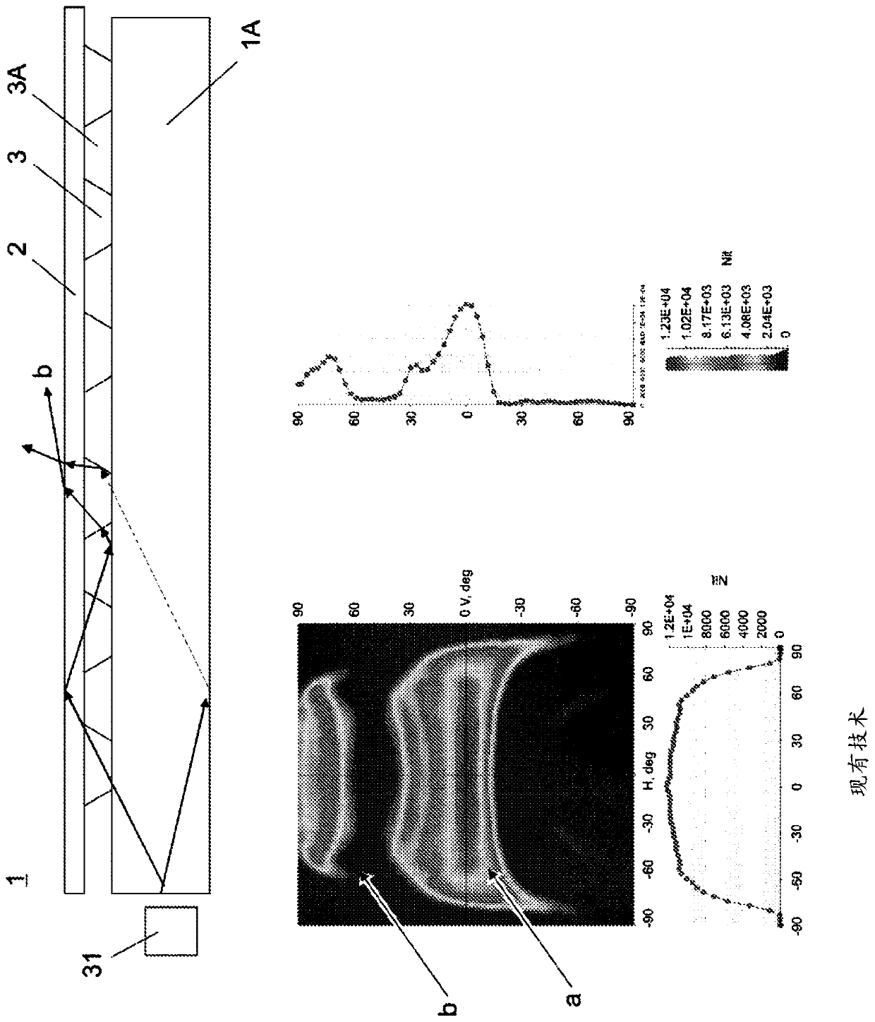
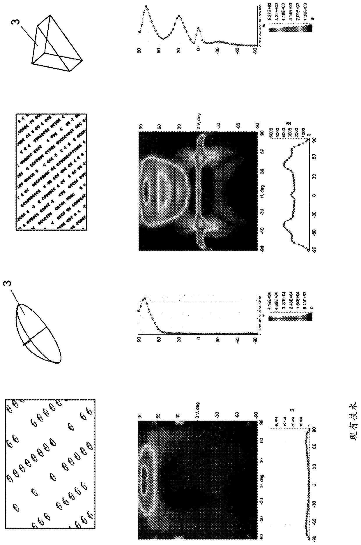
[0075] 1, 1A, 2, 3, 3A – conventional light guides and their components;

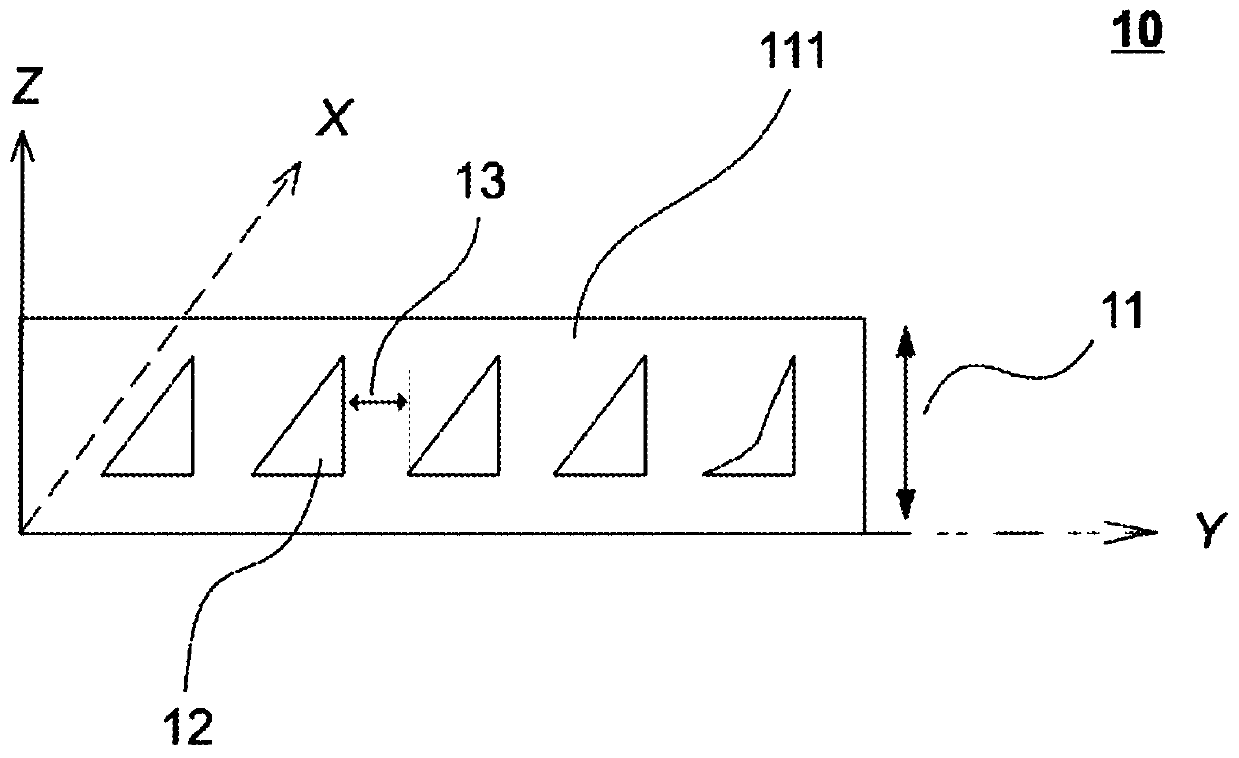
[0076] 10-Light distribution layer structure;

[0077] 11, 11A-optical characteristic pattern;

[0078] 111, 111A - light transmissive carrier medium;

[0079] 12 - Optical (pattern) features;

[0080] 13 - optical channel;

[0081] 121, 122 - optical functional surfaces;

[0082] 100, 100A-light distribution element (light guide);

[0083] 101, 101A - optically transparent substrate;

[0084] 141 - Optical filter surface or layer;

[0085] 141A - holes provided in the surface of the optical filter;

[0086] 151 - adhesive;

[0087] 31 - light source;

[0088] 41 - brightness enhancement film, BEF (prior art);

[0089] 42 - re...


PUM


Abstract

A light distribution structure 10 and a related element 100, such as a light guide, are provided. The structure 10 is preferably an optically functional layer comprising an at least one feature pattern 11, 11A established in a light-transmitting carrier by a plurality of three-dimensional optical features variable in terms of at least one of the cross-sectional profile, dimensions, periodicity, orientation and disposition thereof within the feature pattern. In some instances, the optical features are embodied as internal optical cavities 12 capable to establish the total internal reflection (TIR) function at a horizontal surface and at an essentially vertical surface thereof. A method for manufacturing the light distribution structure is further provided.

Description

technical field [0001] In general, the present invention relates to light transmissive substrate optics. In particular, the present invention relates to light extraction and distribution layer structures for light distribution elements such as light guides, which provide significantly enhanced lighting performance. Background technique [0002] In lighting applications, lighting performance is largely dependent on the light distribution system used. Typical light guide (LG) systems include optical patterns that control light outcoupling efficiency during light extraction. To control the angular distribution of emitted light and achieve the desired performance, traditional light guide solutions designed for lighting / illumination applications still use a number of separate optical films, such as Brightness Enhancement Films (BEF). Therefore, from Figure 1B It can be observed that without a BEF it is not possible to control the light distribution in the desired way with conv...

Claims


Application Information

Patent Timeline
Patent Type & Authority Applications(China)
IPC IPC(8): G02B6/00
CPCG02B6/0036G02B6/0038G02B6/0065G02B6/02038G02B6/02052G02B6/12002
Inventor K.林科
Owner NITTO DENKO CORP
Learn More