Check patentability & draft patents in minutes with Patsnap Eureka AI!

Powder inhalation device

An inhalation device and powder technology, applied in the field of medical devices, can solve the problems of easy pollution, inconvenient use, powder residue, etc., and achieve the effect of avoiding pollution and convenient disassembly

Pending Publication Date: 2020-06-19
SUZHOU SINGMED MEDICAL DEVICE SCI & TECH LTD
View PDF0 Cites 0 Cited by
  • Summary
  • Abstract
  • Description
  • Claims
  • Application Information

AI Technical Summary

Problems solved by technology

The disadvantages of this type of powder inhaler: 1. The amount of powder delivered each time is unstable; 2. The sealing performance of this type of powder inhaler is poor, so the powder is easily affected by moisture in a relatively humid environment, which affects the expected effect; During the separation process in the storage, some powder will remain inside the powder inhaler, which will pollute the powder inhaler and cause certain harm to the user;
This type of powder inhaler better guarantees the tightness of the powder; its disadvantages: 1. Poor repeatability, and there are differences in the delivery of the same powder inhaler to the patient before and after; 2. There will be powder residue inside the powder inhaler , will cause pollution to the powder inhaler, causing certain harm to the user; 3. There will be powder residue in the blister, causing the performance of the powder to fail to achieve the expected effect;
The shortcoming of existing this type of product: one, the reliability of existing powder inhaler is poor; Normal use; 2. The powder inhaler cannot be fully cleaned, which is easy to cause pollution; 3. The use is not humane enough, and the use is not convenient enough; the assembly process is complicated, the defect rate is high, and the manufacturing cost is high

Method used


Image

  • Powder inhalation device
  • Powder inhalation device
  • Powder inhalation device

Examples


Embodiment Construction

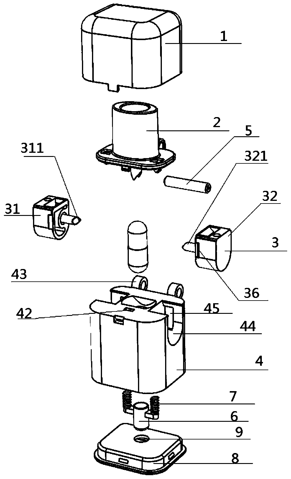
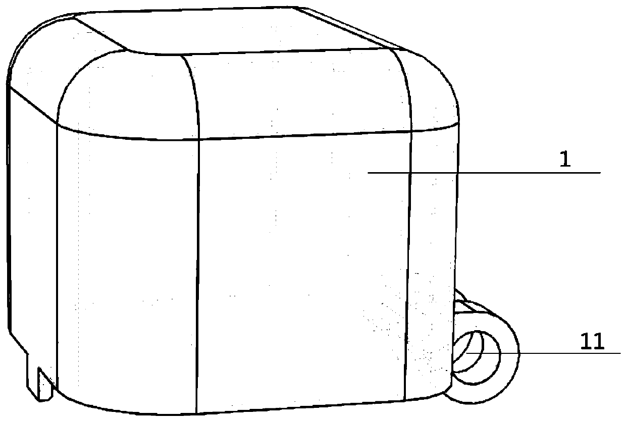
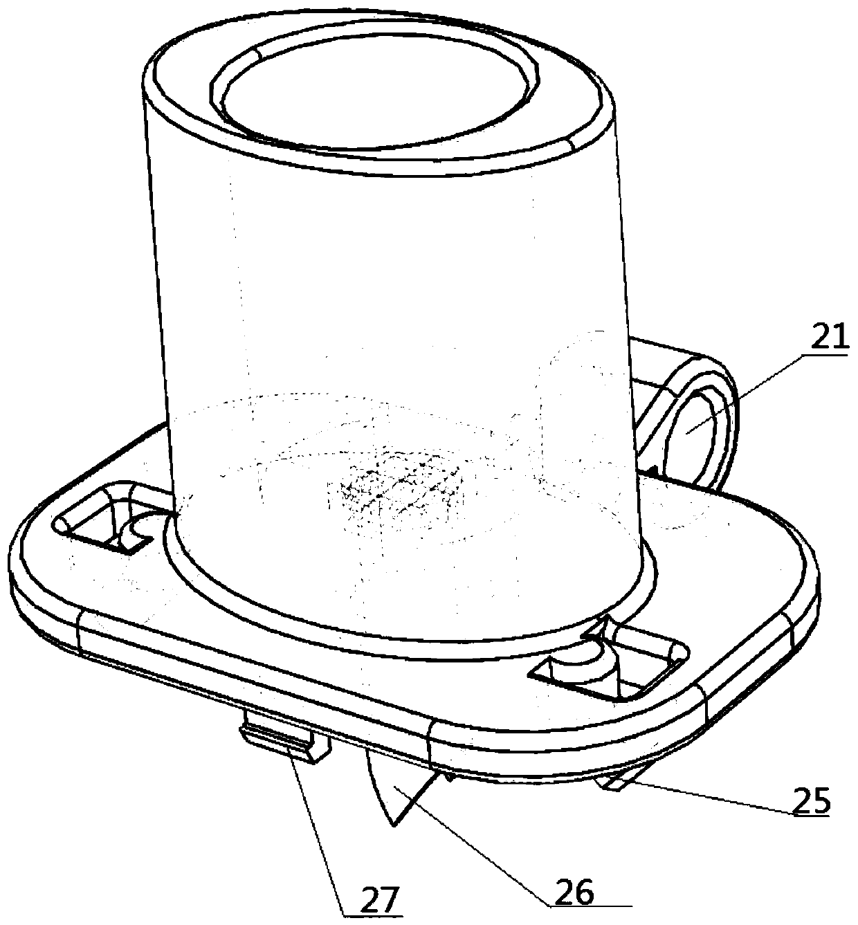
[0031] Such as figure 1 Shown is a schematic structural view of the powder inhalation device of the present invention; as figure 2Shown is a schematic diagram of the structure of the dustproof cover of the powder inhalation device of the present invention. A powder inhalation device, comprising: a dust cover 1, a suction nozzle 2, a button 3, a capsule chamber 4, a capsule seat 6 and a lower cover 8; the dust cover 1 is sleeved on the suction nozzle 2, and the bottom of the suction nozzle 2 is sleeved There is a capsule chamber 4, and a lower cover 8 is socketed under the capsule chamber 4; the button 3 is socketed on the left and right sides of the capsule chamber 4; the center of the capsule chamber 4 is provided with a receiving portion 41 connected up and down; the capsule seat 6 The upper end is provided with an elastic device 7, and the elastic device 7 is placed in the receiving portion 41, and the lower end of the capsule seat 6 is placed in the circular hole 81 prov...


PUM


Abstract

The invention discloses a powder inhalation device which comprises a dustproof cover, an inhalation mouth, buttons, a capsule cabin, a capsule holder and a lower cover, wherein the buttons comprise aleft button and a right button; air inlets are formed in the upper ends of the left button and the right button; a second hollow puncture needle is arranged on the inner side wall of the left button;the second hollow puncture needle communicates with the air inlet of the left button; a third hollow puncture needle is arranged on the inner side wall of the right button; the third hollow puncture needle communicates with the air inlet in the right button; the second hollow puncture needle and the third hollow puncture needle are not on a same axis; and a first hollow puncture needle communicating with an air flow channel is arranged below the inhalation mouth. A capsule is punctured through the first hollow puncture needle, the second hollow puncture needle and the third hollow puncture needle, air feeding is implemented through the air inlets, air flows around the outer wall of the first hollow puncture needle to form spiral air flows which are baffled after reaching the bottom of thecapsule cabin, and the air flows move upwards to drive powder in the capsule to finally enter a human body from the inner wall of the first hollow puncture needle.

Description

technical field [0001] The invention relates to the field of medical devices, more specifically, to a powder inhalation device. Background technique [0002] In the known powder inhaler technical field, there are various powder inhalers, and the existing powder inhalers can be divided into three categories: [0003] The first type: the powder inhaler of the storage type, which has a storage tank inside which can store a certain dose of powder. A dose of powder is then separated and the powder is inhaled into the patient through an exhaust tube. The disadvantages of this type of powder inhaler: 1. The amount of powder delivered each time is unstable; 2. The sealing performance of this type of powder inhaler is poor, so the powder is easily affected by moisture in a relatively humid environment, which affects the expected effect; During the separation process in the storage, some powder will remain inside the powder inhaler, which will pollute the powder inhaler and cause ce...

Claims


Application Information

Patent Timeline
Patent Type & Authority Applications(China)
IPC IPC(8): A61M15/00
CPCA61M15/00A61M15/0001A61M15/0025A61M15/003A61M15/0036A61M15/0043
Inventor 黄芬任瑞贤
Owner SUZHOU SINGMED MEDICAL DEVICE SCI & TECH LTD
Features
  • R&D
  • Intellectual Property
  • Life Sciences
  • Materials
  • Tech Scout
  • Unparalleled Data Quality
  • Higher Quality Content
  • 60% Fewer Hallucinations
Learn More