
Mounting machine and mounting process for clamp, rubber tube and joint

A technology for installing machines and hoses, applied in the field of machinery and equipment, can solve the problems of high labor intensity of workers, the output cannot meet the requirements, and the errors are large, and achieve the effect of saving labor costs, improving production efficiency, and saving labor costs.

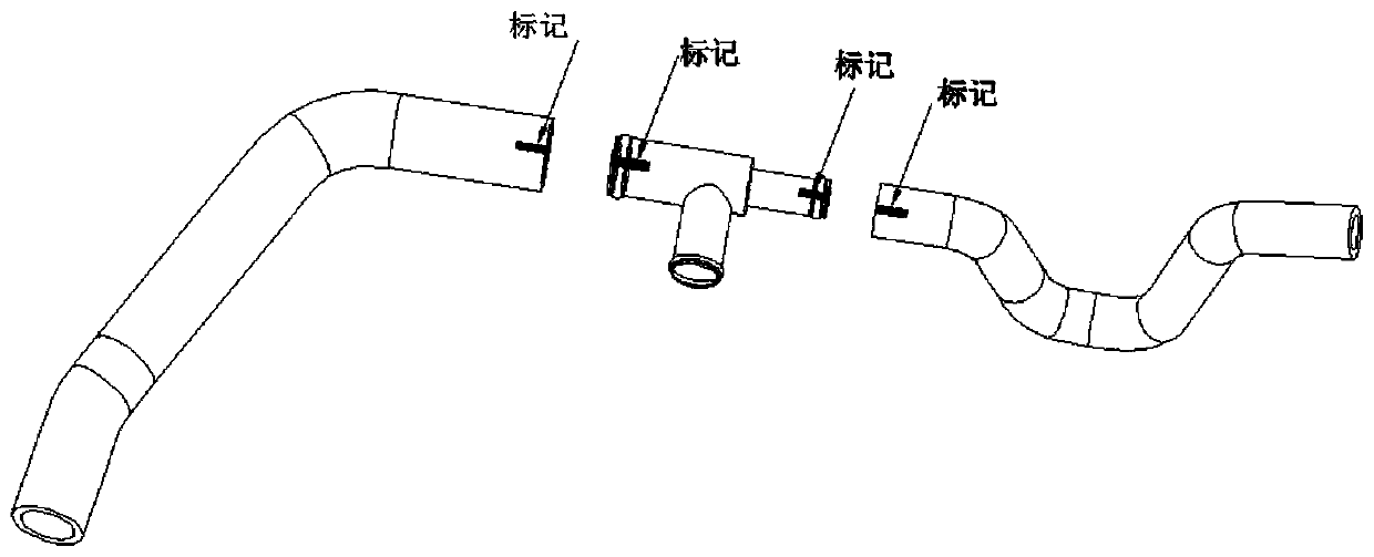
Pending Publication Date: 2020-06-19
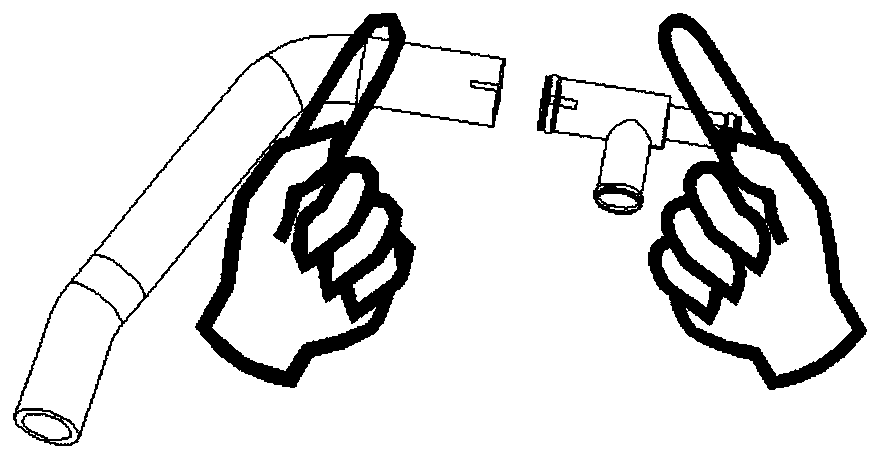
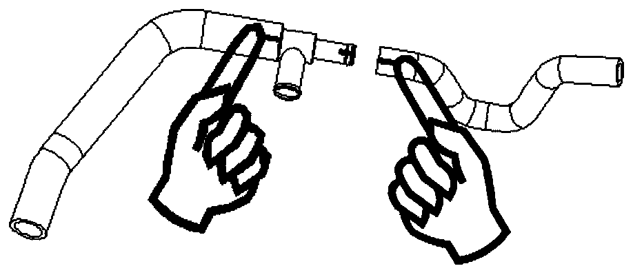
四川省胜顺鸿兴模具有限公司
View PDF0 Cites 7 Cited by
  • Summary
  • Abstract
  • Description
  • Claims
  • Application Information

AI Technical Summary

Problems solved by technology

[0009] 1. slow
[0010] 2. Many people
[0011] 3. There is a deviation from the actual product angle
The workers refer to the drawings and do not have any angle positioning tools to control. They draw marking lines on the approximate positions of the hoses, joints, and clamps for manual assembly. The error is too large
[0012] 4. The output of the customer is large, but the output cannot meet the requirements
[0013] 5. Manual assembly is adopted, and the labor intensity of workers is high

Method used


Image

  • Mounting machine and mounting process for clamp, rubber tube and joint
  • Mounting machine and mounting process for clamp, rubber tube and joint
  • Mounting machine and mounting process for clamp, rubber tube and joint

Examples


Embodiment 1

[0060] like Figure 2-3 As shown, a clamp-hose-joint installation machine of the present invention includes a workbench 1, a shelf 2, a bottom cabinet 3, a Foma wheel 4, a fan 5, and a lamp 6.

[0061] The bottom cabinet 3 is a cuboid cabinet. The door leaf of the cabinet is Q235 after plastic spraying treatment. Fuma wheels 4 are installed at the bottom four corners of the bottom cabinet 3. The workbench 1 is installed on the top of the bottom cabinet 3. The back of the bottom cabinet 3 Install the shelf 2, the shelf 2 is made of lapped profiles, the height of the shelf 2 is higher than the workbench 1, the shelf 2 forms an inverted L-shaped structure, and the operation instructions for the installation of the clamp and the hose are pasted on the vertical part, extending horizontally A fan 5 and a lamp tube 6 are installed on the section for providing heat dissipation and lighting when operating on the workbench 1 .

[0062] like Figure 4 As shown, workbench 1 is equipped ...

Embodiment 5

[0082] like Figure 7-13 As shown, a clamp-hose-joint installation process includes the following steps:

[0083] Step 1. Put clamp A9 into the profiling groove of clamp angle positioning mold A119, put clamp B10 into the profiling groove of clamp angle positioning mold B120, start clamp angle positioning mold A119 and Position the mold B120 at the clamp angle, and spread the clamp A9 and the clamp B10 apart.

[0084]Step 2. Workers manually separate the hose angle positioning upper mold A110 from the hose angle positioning lower mold A113, separate the joint angle positioning upper mold 112 from the joint angle positioning lower mold 115, and separate the hose angle positioning upper mold B111 from the hose angle positioning lower mold Die B114 separates.

[0085] Step 3. Put the hose A11 into the profiling groove of the mold A113 under the angle positioning of the hose, put the joint 13 into the profiling groove of the mold 115 under the angle positioning of the joint, and...


PUM


Abstract

The invention provides a mounting machine and a mounting process for a clamp, a rubber tube and a joint. The mounting machine comprises a workbench and a bottom cabinet, wherein the workbench is mounted on the bottom cabinet, a joint angle positioning die, a rubber tube angle positioning die, a clamp angle positioning die and a slide rail are mounted on the workbench, the middle of the slide railis used for installing the joint angle positioning die, the two sides of the joint angle positioning die are provided with the rubber tube angle positioning die and the clamp angle positioning die correspondingly, all positioning die bottom plates are installed on the slide rail, and all the positioning dies are provided with profiling grooves used for installing the rubber tube, the joint and theclamp correspondingly. According to the machine and the process, the speed is high, one assembly can be completed within 10 s, the number of workers is small, only one worker is needed for completingthe assembly, the product accuracy is high, deviation is avoided, the drawing requirement can be met, operation is easy, full-automatic assembly is achieved, and the labor intensity of the worker isrelieved.

Description

technical field [0001] The invention belongs to the technical field of mechanical equipment, and in particular relates to a clamp-hose-joint installation machine and an installation process. Background technique [0002] like Figure 1(a)-Figure 1(f) As shown, the steps to realize clamp-hose-joint installation in the prior art are: [0003] 1. The first person clamps the clamp with the clamp insert and puts it into the rubber hose (the worker marks the rubber hose and the joint respectively according to the assembly direction of the drawing). [0004] 2. The second person puts the left rubber hose into the joint (workers manually install the rubber hoses on both sides on the joint according to the marks). [0005] 3. The third person puts the right rubber hose into the joint (workers use clamp pliers to open the clamp and move the clamp to the assembly place). [0006] 4. The fourth person is used for clamp insertion to clamp the clamp to the corresponding position and adj...

Claims


Application Information

Patent Timeline
Patent Type & Authority Applications(China)
IPC IPC(8): B23P21/00
CPCB23P21/004
Inventor 张光西
Owner 四川省胜顺鸿兴模具有限公司
Learn More