
Unmanned ship with full-revolving steering oar
A full-turn, unmanned ship technology, applied in unmanned surface ships, ship construction, ship propulsion, etc., can solve problems such as poor maneuverability, difficult maneuvering, and trouble
- Summary
- Abstract
- Description
- Claims
- Application Information
AI Technical Summary
Problems solved by technology
Method used
Image

Examples
Embodiment Construction
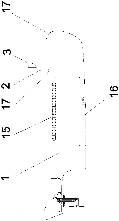
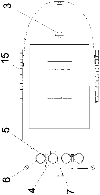
[0014] The specific implementation manner of the present invention will be described below with reference to the accompanying drawings. Such as figure 1 , figure 2 , image 3 Shown: a full-turn rudder oar unmanned ship, including a hull 1 as a base, an electric pan-tilt 2 is arranged at the bow of the hull 1, a camera 3 is arranged on the electric pan-tilt 2, and the hull 1 Two sets of full-turn steering gears are arranged symmetrically at the stern,
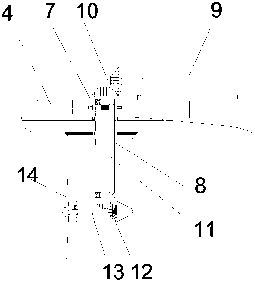
[0015] The full-turn steering gear includes a rotary motor 4 fixed in the hull 1, a worm 5 is connected to the working end of the rotary motor 4, and the worm 5 is meshed with the balance worm wheel 6 and the rotary worm wheel 7 at the same time. The balance worm gear 6 and the rotating worm gear 7 are symmetrically distributed, the inner ring of the rotating worm gear 7 is connected to the top of the rotating housing 8, and the rotating housing 8 is rotatably supported on the bottom plate of the hull 1. The bottom of 8 is ...
PUM
 Abstract
Description
Claims
Application Information