Anti-collision device of overline T-shaped beam bridge and mounting method thereof

An anti-collision device and cross-line technology, which is applied to road safety devices, bridges, bridge parts, etc., can solve problems such as side main beam damage, and achieve the effects of easy manufacture and installation, easy installation, maintenance and replacement, and low cost

Pending Publication Date: 2020-06-19
ZHENGZHOU UNIV
View PDF0 Cites 0 Cited by
  • Summary
  • Abstract
  • Description
  • Claims
  • Application Information

AI Technical Summary

Problems solved by technology

Because the impact force is a concentrated force, it generally acts on the local impact point. If energy absorbing materials or energy-dissipating materials are arranged near the impact point, a large impact force will still be transmitted to the side girder web for a large impact energy. damage the side girder

Method used


Image

  • Anti-collision device of overline T-shaped beam bridge and mounting method thereof
  • Anti-collision device of overline T-shaped beam bridge and mounting method thereof
  • Anti-collision device of overline T-shaped beam bridge and mounting method thereof

Examples


Embodiment 1

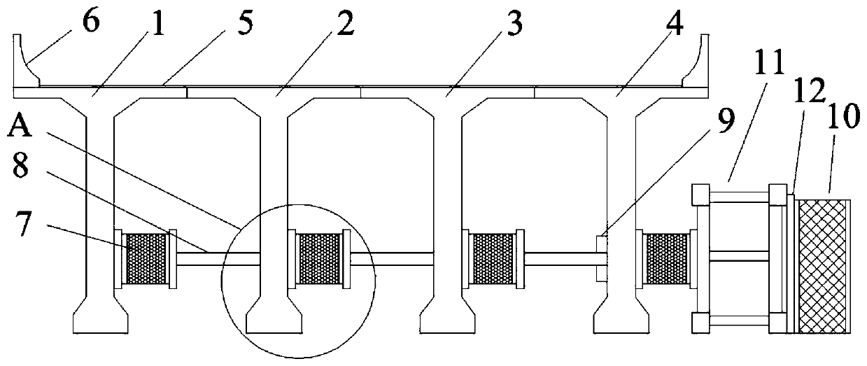
[0048] figure 1 It is a schematic diagram of the front view of the longitudinal bridge of the anti-collision device in this embodiment. The T-beam bridge is a four-beam simply supported T-beam bridge with a span length of 20m and only one-way vehicles. The bridge consists of 4 prefabricated T-beams arranged side by side, and the adjacent upper flanges are connected into one body through on-site wet joints, which can be divided into the first main beam 1, the second main beam 2, the third main beam 3 and the fourth main beam. The beam 4 has a bridge deck layer 5 on it, and reinforced concrete guardrails 6 are arranged on both sides of the bridge deck. The bridge deck layer 5 is composed of 80mm thick C50 concrete, waterproof layer, 100mm thick asphalt concrete from bottom to top, and a 1% transverse slope is provided to one side. The height of the main beam is 1500mm, the overall width is 2000mm, the net distance between each main beam is 1800mm, the width of the web above the...

Embodiment 2

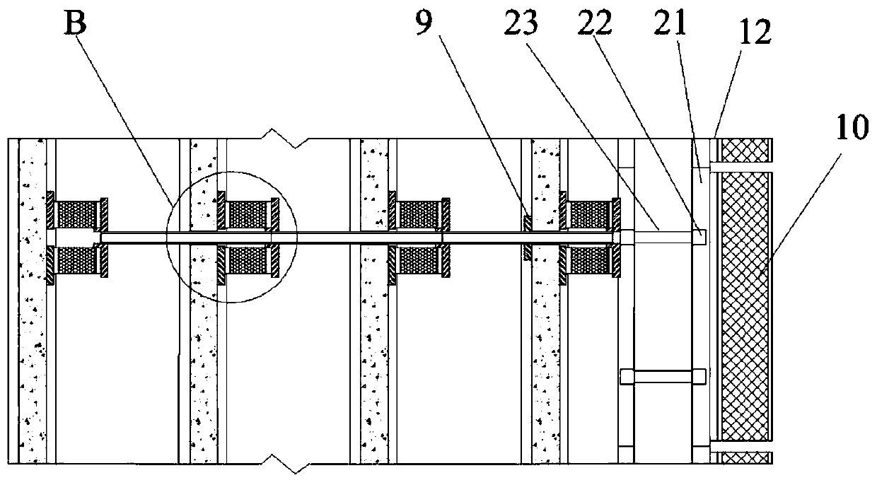
[0059] The difference between this embodiment and Embodiment 1 is that there are two layers of energy-consuming units in the vertical direction. For details, see Figure 12 , to facilitate the consumption of large impact energy. The specification of vertical bar 22 is identical with horizontal bar 21, and length is 800mm, and whole anti-collision frame 11 height is 1000mm. 820mm from the center of the force transmission hole 13 on the upper floor to the bottom surface of the main beam.

Embodiment 3

[0061] The difference between this embodiment and Embodiment 1 is that the number of energy-consuming components 7 of each energy-consuming unit is not equal. For details, see Figure 13 . Considering that the probability of super-high vehicles appearing on the right side of the lower road is greater, the number of energy-consuming components 7 of the corresponding energy-consuming unit is 4, while the number of energy-consuming components 7 of the energy-consuming unit on the other side is gradually reduced to 3 1 and 2, make the anti-collision device more targeted.


PUM


Abstract

The invention discloses an anti-collision device of an overline T-shaped beam bridge and a mounting method thereof, and mainly aims to prevent large damage when a side main beam is impacted by an ultrahigh vehicle. The anti-collision device comprises a buffer plate which is directly impacted, an anti-collision frame on a rear side of the buffer plate, and a plurality of energy consumption units which are connected with the anti-collision frame and arranged side by side in the longitudinal direction of the bridge, wherein each energy dissipation unit is arranged in the transverse direction of the bridge and comprises a plurality of energy dissipation assemblies and force transmission rods for connecting the energy dissipation assemblies in series, and the energy dissipation assembly is fixed to a main beam web. The anti-collision device is advantaged in that the buffer plate of the anti-collision device firstly consumes part of energy, an anti-collision frame disperses the received local impact to the energy consumption units of the whole bridge span, and the energy consumption unit consumes energy and distributes the impact force to each main beam; if the impact energy is very large, the anti-collision frame can be deformed and even damaged, so the energy is consumed. The anti-collision device is designed in a unitization and modularization mode, convenient to install, maintainand replace and low in manufacturing cost.

Description

technical field [0001] The invention relates to the technical fields of bridge engineering and river-crossing engineering, in particular to an anti-collision device and an installation method of a line-span T-beam bridge. Background technique [0002] Bridges are the infrastructure of national transportation and the link of national economic circulation. With the rapid development of the market economy, many three-dimensional transportation facilities have been built, and many cross-line bridges have appeared. Over-the-line bridges across railways, expressways, provincial roads, national roads, and waterways can be seen everywhere. However, in recent years, due to the headroom of the old bridges, the height of the existing large vehicles is not enough; the vehicle height limit logo pattern is not eye-catching enough, and the location is not scientific enough; the driver's traffic safety awareness is not enough and they run illegally; the traffic control department lacks sup...

Claims


Application Information

Patent Timeline
Patent Type & Authority Applications(China)
IPC IPC(8): E01F15/14E01D2/00E01D2/04E01D19/00E01D21/00F16F15/08
CPCE01F15/14E01F15/146E01D2/00E01D2/04E01D19/00E01D21/00F16F15/08
Inventor 魏建东刘忠玉王利齐清华
Owner ZHENGZHOU UNIV
Why Eureka
Try Eureka