
Residue processing device

A technology for treating equipment and residues, applied in water supply equipment, indoor sanitary pipeline installations, buildings, etc., can solve the problems of machine weight, high cost, coarse grinding particles, etc., and achieve simple structure, simple and hygienic operation, and convenient installation Effect

Pending Publication Date: 2020-06-19
SMARTFISH TECH
View PDF0 Cites 2 Cited by
  • Summary
  • Abstract
  • Description
  • Claims
  • Application Information

AI Technical Summary

Problems solved by technology

A food waste disposer is a solution to the above problems. The existing food waste disposer uses a rotating cutter head to drive the residue to rotate, and throws it to the side wall under the action of centrifugal force. The grinding block on the cutter head and the side wall The holes form a shearing action to grind the residue. The disadvantage is that the whole machine is heavy, the grinding particles are coarse, and the cost is high.

Method used

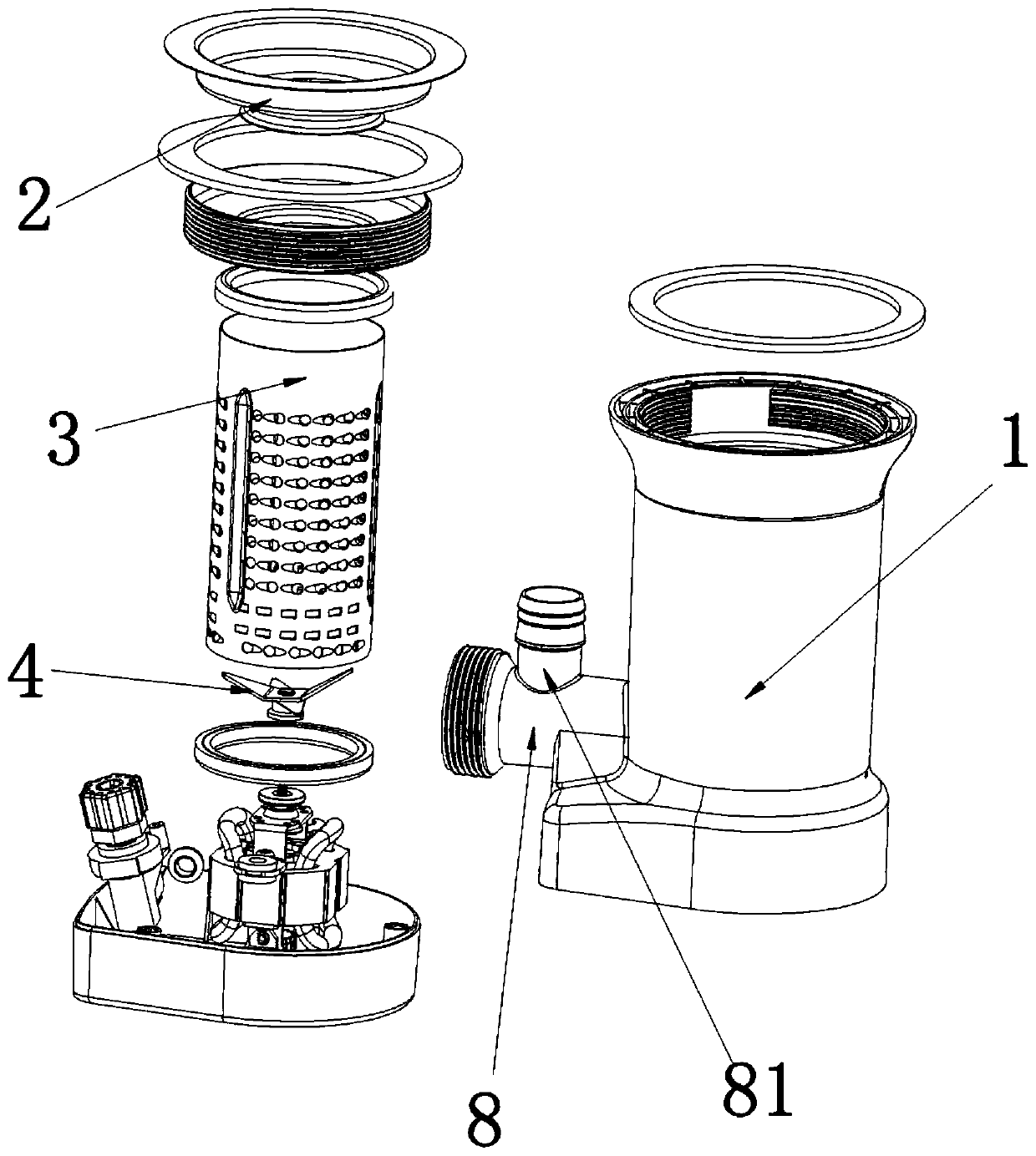
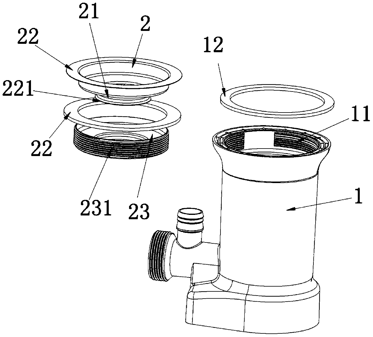
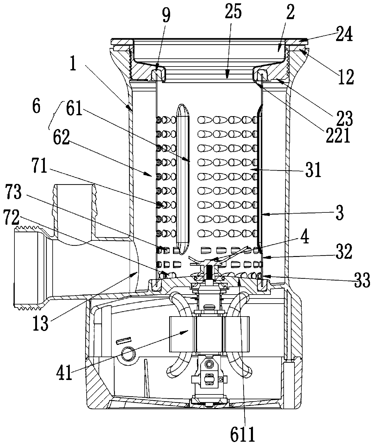

Image

  • Residue processing device
  • Residue processing device
  • Residue processing device

Examples


Embodiment Construction

[0026] The present invention will be further described in conjunction with the following examples.

[0027] A specific embodiment of the residue processing device of the present invention, such as figure 1 with image 3 As shown, it includes a flow guide 2, a housing 1 and a filter cartridge 3. The housing 1 is provided with a liquid discharge port 13 for discharging residue. In the middle of the deflector 2 is provided a deflector 25 for the residue to pass through.

[0028] In this embodiment, in order to facilitate the removal and installation of the residue processing device, the air guide 2 is detachably mounted on the top of the housing 1 to jointly enclose the processing cavity 6. Please see figure 2 The flow guide 2 includes a vertical flow guide 21 and a lip 22 located at the top end of the flow guide 21 and extending outward. In the assembled state, the guide portion 21 of the guide member 2 is fixedly connected to the inside of the housing 1, and a clamping space is f...


PUM


Abstract

The invention relates to the technical field of residue processing, in particular to a residue processing device. The residue processing device comprises a diversion piece, a shell and a filter barrel; the diversion piece is detachably installed at the top end of the shell so that the diversion piece and the shell can jointly form a processing cavity; the filter barrel is fixedly installed in theshell so that that the processing cavity can be divided into an inner cavity located in the filter barrel, and an outer cavity located between the filter barrel and the inner wall of the shell, and the side wall of the filter barrel is provided with a plurality of filter holes distributed at intervals; the diversion piece is provided with a diversion opening communicating with the inner cavity; the inner cavity is internally provided with a smashing cutter used for smashing residues; and the shell is provided with a liquid outlet communicating with the outer cavity. Compared with the prior art, the residue processing device is simple in structure, convenient to install, easy and convenient to operate and sanitary, the trouble that the residues need to be processed through hands is avoided,the effects of side wall grinding and high-speed cutting blade smashing are achieved, in addition, the effect that the particle size of the residues or mediums meets the discharge requirement can beeffectively ensured by arranging the filter barrel, the situation that a drainage pipe is blocked due to the fact that the size of the residues is too large is avoided, and the residue processing quality is ensured.

Description

Technical field [0001] The invention relates to the technical field of residue treatment, in particular to a residue treatment device. Background technique [0002] The sink is a container that people use to clean various objects, and it is widely used, but it is used in the kitchen in the home. The sink is generally equipped with a drainage device, and the water is discharged into the sewer through the drainage device. [0003] In practical applications, large objects or residues fall into the sewer pipe, which can easily cause the sewer to be blocked. In order to prevent this problem from occurring, in the prior art, a sewer with filtering function is installed at the drain of the sink. , The opening of the drain is much larger than that of ordinary pipes. Put a filter or a cage with filtering function inside it, so that the larger residue can only stay in the filter or cage. When cleaning, the user will The lifting cage and filter are lifted and discarded. Although this solves...

Claims


Application Information

Patent Timeline
Patent Type & Authority Applications(China)
IPC IPC(8): E03C1/266E03C1/264
CPCE03C1/2665E03C1/264
Inventor 卢小平
Owner SMARTFISH TECH
Learn More