A magneto-rheological fluid pilot pressure reducing valve

A pilot-operated decompression valve and magneto-rheological fluid technology, which is applied in the field of magnetic flow valves, can solve the problems of reduced magnetic induction intensity, blockage of damping gaps, and reduced pressure difference between the inlet and outlet of magnetorheological valves, achieving low machining accuracy and convenient operation. Wide range of disassembly and assembly and differential pressure adjustment

Active Publication Date: 2021-04-16
CHINA UNIV OF MINING & TECH
View PDF6 Cites 0 Cited by
  • Summary
  • Abstract
  • Description
  • Claims
  • Application Information

AI Technical Summary

Problems solved by technology

However, when the width of the damping gap is too small, the damping gap will be blocked, and the damping gap is not perpendicular to the direction of the magnetic induction line, and its magnetic induction intensity will decrease, which in turn will reduce the pressure difference between the inlet and outlet of the magnetorheological valve.

Method used


Image

  • A magneto-rheological fluid pilot pressure reducing valve
  • A magneto-rheological fluid pilot pressure reducing valve
  • A magneto-rheological fluid pilot pressure reducing valve

Examples


Embodiment Construction

[0025] The following will clearly and completely describe the technical solutions in the embodiments of the present invention with reference to the accompanying drawings in the embodiments of the present invention. Obviously, the described embodiments are only some, not all, embodiments of the present invention. Based on the embodiments of the present invention, all other embodiments obtained by persons of ordinary skill in the art without making creative efforts belong to the protection scope of the present invention.

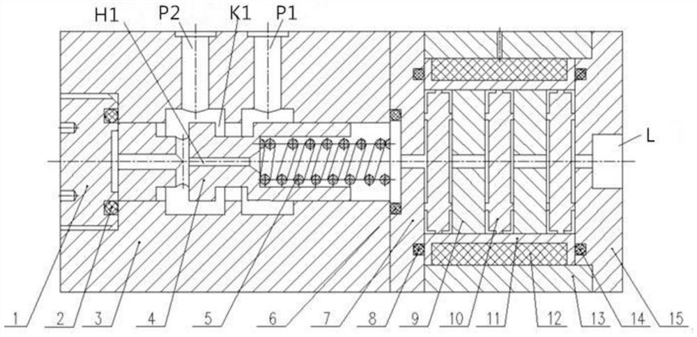
[0026] like figure 1 As shown, a magneto-rheological fluid pilot pressure reducing valve includes a main valve and a magneto-rheological pilot valve. The main valve includes a main valve body 3. The main valve body 3 is provided with a cavity that runs through front and back and its rear end is threaded. Connected with the sealing rear screw cover 1, the sealing rear screw cover 11 and the main valve body 3 are sealed by the sealing ring I2, and the main valve...


PUM


Abstract

The invention discloses a magneto-rheological fluid pilot pressure reducing valve, which comprises a main valve body, a main valve core, a spring, a valve seat, a damping disc, a bobbin frame, a coil and a valve sleeve; the main valve includes two left and right cavities Body, the left chamber communicates with the oil outlet, the right chamber communicates with the oil inlet, and the valve port is normally open; the left chamber communicates with the front chamber of the magnetorheological pilot valve through the damping hole, and the main valve core and the inner surface of the main valve form a moving pair; In the magneto-rheological pilot valve, the liquid flow channel between the winding frame, the positioning disc and the damping disc forms an axial and radial damping gap. When the coil of the magneto-rheological pilot valve is energized, the magnetic force line passes through the damping gap vertically, and the magnetic flow Under the action of the magnetic field, the viscosity of variable fluid increases rapidly; by adjusting the magnitude of the current, the pressure difference at both ends of the damping gap can be changed; the magnetorheological pilot valve has no moving spool, simple structure, and high control precision.

Description

technical field [0001] The invention relates to the field of magnetic flow valves, in particular to a magneto-rheological fluid pilot pressure reducing valve. Background technique [0002] Traditional control valves contain mechanical parts that can move with each other to complete the control of system pressure and flow. Sometimes, in order to improve the response speed and work performance of the valve, valve sleeves are often installed in the mechanical parts, which leads to the traditional The structure of the hydraulic valve is complex and the size is large. At the same time, due to the existence of movable parts, the friction and wear of the parts will be aggravated, which will lead to inaccurate moving positions, easy to cause leakage and reduce work efficiency. Due to the existence of moving pairs, the machining accuracy of each part High, resulting in high cost, but also has defects such as difficult control and slow response. [0003] The magnetorheological valve ...

Claims


Application Information

Patent Timeline
Patent Type & Authority Patents(China)
IPC IPC(8): F15B13/02
CPCF15B13/025
Inventor 谢方伟郁程程田祖织刘秀梅沈刚丁志文
Owner CHINA UNIV OF MINING & TECH
Why Eureka
Try Eureka