Hydraulic oil purification system

A purification system and hydraulic oil technology, which is applied to fluid pressure actuation system components, fluid pressure actuation devices, mechanical equipment, etc., can solve the problems of long time, oil waste, and many processes, so as to improve fluidity and improve Separation efficiency, the effect of improving separation efficiency

Inactive Publication Date: 2020-06-19
重庆凯装自动化设备有限公司
View PDF9 Cites 0 Cited by
  • Summary
  • Abstract
  • Description
  • Claims
  • Application Information

AI Technical Summary

Problems solved by technology

Great waste of oil
The traditional method of heating to 100°C to allow the water to evaporate by itself requires a long time and many processes

Method used


Image

  • Hydraulic oil purification system

Examples


Embodiment Construction

[0026] In this embodiment, the orientation or positional relationship indicated by the terms "upper", "lower", "left", "right", "front", "rear", "upper end" and "lower end" are based on the orientation or positional relationship shown in the drawings, It is for the convenience of description only, and does not indicate or imply that the device or element referred to must have a specific orientation, be constructed in a specific orientation, or operate, and thus should not be construed as limiting the invention.

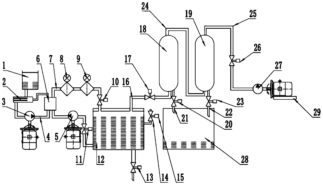
[0027] see figure 1 , a hydraulic oil purification system. It includes an oil storage tank 12, which is closed and used to store hydraulic oil. The closed oil storage tank 12 is arranged with a hydraulic oil circulation circuit 7, a vacuum negative pressure pipeline 16, a refueling pipe 14, an oil discharge pipeline, and an oil discharge cut-off valve 13 is arranged on the oil discharge pipeline. The hydraulic oil circulation circuit 7 is arranged with a hydraulic o...


PUM


Abstract

The invention discloses a hydraulic oil purification system. According to the hydraulic oil purification system, an oil-water mixture can be quickly separated. The hydraulic oil purification system comprises an oil storage tank used for storing hydraulic oil, an oil adding pipeline used for inputting the hydraulic oil into the oil storage tank, a heating pipeline used for heating the hydraulic oilin the oil storage tank, and a vacuum negative pressure pipeline used for pumping out water vapor generated in the oil storage tank.

Description

technical field [0001] The invention relates to the field of hydraulic technology, in particular to a hydraulic oil purification system. Background technique [0002] Hydraulic oil is used as the medium for the normal operation of the hydraulic system. If it is used in the system for a long time, impurities in the hydraulic system will appear in the hydraulic oil, which will cause the hydraulic system to fail to work properly over time. At the same time, in the long-term work of the hydraulic system, especially for the hydraulic system with high and low temperature environment, water will appear in the hydraulic oil, resulting in oil emulsification. prevent the system from functioning properly. In response to this situation, especially oil emulsification, there is often a means to change the oil. Causes a great waste of oil. The traditional method of heating to 100°C to allow the water to evaporate by itself takes a long time and involves many processes. Contents of th...

Claims


Application Information

Patent Timeline
Patent Type & Authority Applications(China)
IPC IPC(8): F15B21/041F15B21/0427F15B21/044
CPCF15B21/041F15B21/0427F15B21/044
Inventor 刘超唐国义陈世林
Owner 重庆凯装自动化设备有限公司
Why Eureka
Try Eureka