Frame type direct copper-ceramic bonding plate and manufacturing method thereof

A technology of ceramic copper clad laminate and manufacturing method, which is applied in semiconductor/solid-state device manufacturing, electrical components, electrical solid-state devices, etc., can solve the problems of complex installation procedures, easy aging and deterioration of bonding agent, and aging and deterioration of bonding agent, and achieves a simple process. Convenience, avoid aging deterioration, durable bonding and sealing effect

Inactive Publication Date: 2012-02-29
TONG HSING ELECTRONICS IND LTD
View PDF0 Cites 0 Cited by
  • Summary
  • Abstract
  • Description
  • Claims
  • Application Information

AI Technical Summary

Problems solved by technology

[0004] The problem to be solved by the present invention is the problem of aging and deterioration of the bonding agent caused by the fixing of the ceramic frame by the bonding agent, and the problem that the installation procedure is complicated because the metal frame must be insulated.
[0005] The means of the present invention to solve the above-mentioned problems is to directly fix a ceramic frame on a copper-clad ceramic substrate by thermal bonding, thereby avoiding the use of bonding agent and solving the problem that the bonding agent is easy to age and deteriorate. Moreover, Compared with the metal frame, the self-insulating ceramic frame does not need to consider the problem of short circuit, which makes the installation process easier

Method used


Image

  • Frame type direct copper-ceramic bonding plate and manufacturing method thereof
  • Frame type direct copper-ceramic bonding plate and manufacturing method thereof
  • Frame type direct copper-ceramic bonding plate and manufacturing method thereof

Examples


Embodiment Construction

[0029] The present invention will be described in detail below in conjunction with the accompanying drawings and embodiments.

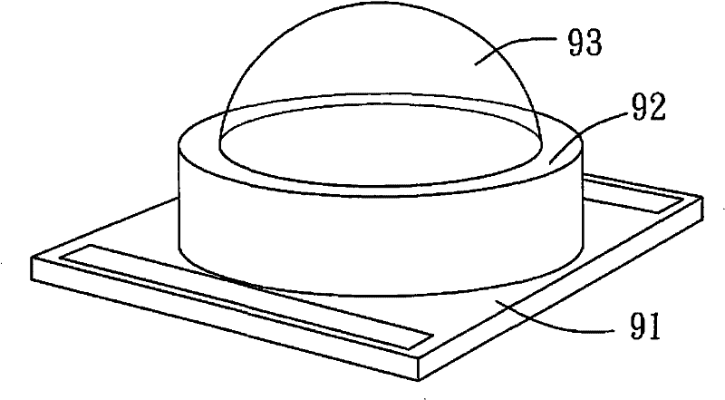
[0030] refer to Figure 2 to Figure 5 , illustrating a method for manufacturing a frame-type ceramic copper-clad laminate and a preferred embodiment of the frame-type ceramic copper-clad laminate of the present invention.

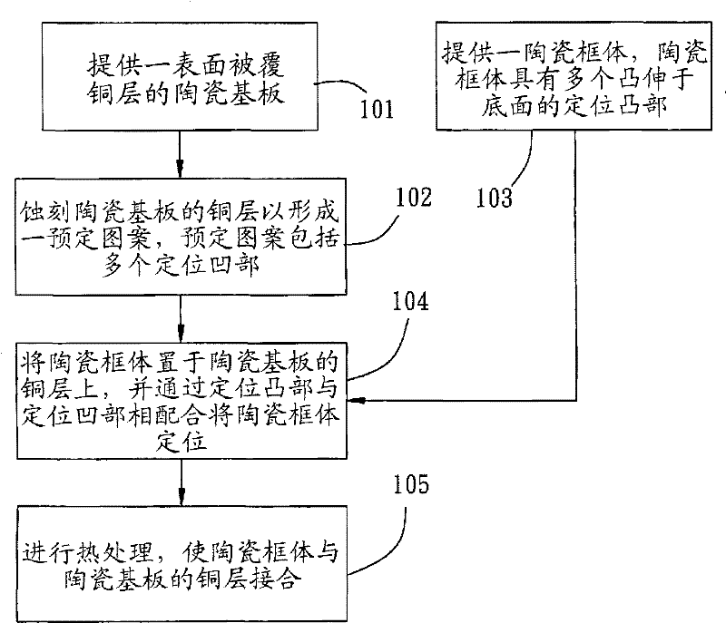
[0031] figure 2 Shown is to make frame-type ceramic copper-clad laminate 100 (such as Figure 5 Shown) is a flow chart of the implementation steps, detailed as follows:

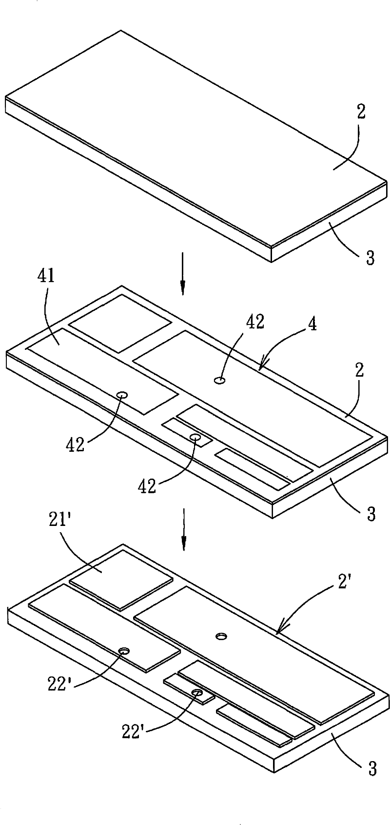
[0032] Cooperate with reference image 3 , as described in step 101, a ceramic substrate 3 whose surface is coated with a copper layer 2 is firstly provided. In this embodiment, the material of the ceramic substrate 3 is alumina, and the copper layer 2 is bonded to the ceramic substrate 3 by direct copper bonding (DBC) , although this embodiment cites a ceramic substrate 3 with a single-sided copper layer 2, a ceramic substrate with a double-sided copper laye...


PUM


Abstract

The invention discloses a frame type direct copper-ceramic bonding plate and a manufacturing method thereof. The frame type direct copper-ceramic bonding plate comprises a ceramic substrate and a ceramic frame; the ceramic frame is covered on the ceramic substrate, provided with a copper layer with preset patterns and a bottom surface, and bonded with the copper layer. The manufacturing method ofthe frame type direct copper-ceramic bonding plate comprises the following steps of: firstly, etching the copper layer to form a preset pattern with a plurality of positioning grooves on the ceramic substrate of which the surface is bonded with the copper layer; secondly, forming positioning projections corresponding to the positioning grooves at the bottom of the ceramic frame, and arranging theceramic frame on the ceramic substrate; thirdly, positioning the ceramic frame by the positioning projections and the positioning grooves, thermally treating the ceramic frame, directly bonding the ceramic frame and the copper layer to fix the ceramic frame on the ceramic substrate. Thus, the invention has no need of using an adhesive and avoids the ageing and the deterioration of the adhesive, so that the bonding performance and the sealing performance of the ceramic frame and the ceramic substrate are more stable.

Description

technical field [0001] The invention relates to a frame-type ceramic copper-clad board and a manufacturing method thereof, in particular to a frame-type ceramic copper-clad board in which a ceramic frame is directly bonded on a copper-clad ceramic substrate and a manufacturing method thereof. Background technique [0002] In order to prevent the electronic components from being affected by moisture or contamination and affect their electrical functions, the electronic components need to be packaged for protection, especially semiconductor components, such as light-emitting diodes (LEDs), which are usually packaged to increase their service life. [0003] refer to figure 1 , a common LED packaging structure, a frame 92 is provided on a substrate 91 to house a chip (not shown), and a lens 93 is covered to seal the chip therein. Generally, the substrate 91 can be a ceramic board on which circuit patterns are provided for electrical connection of chips. The frame body 92 can b...

Claims


Application Information

Patent Timeline
Patent Type & Authority Patents(China)
IPC IPC(8): H01L21/48H01L23/15H01L23/13H01L23/48
Inventor 江文忠吴耿忠谢英基吕政刚傅铭煌
Owner TONG HSING ELECTRONICS IND LTD
Why Eureka
Try Eureka