Bearing cable structure

A cable structure and bearing technology, applied in the field of bearing cable structure, can solve problems such as falling and affecting the panel manufacturing process

Pending Publication Date: 2020-06-19
BEIJING XINLI MACHINERY
View PDF0 Cites 0 Cited by
  • Summary
  • Abstract
  • Description
  • Claims
  • Application Information

AI Technical Summary

Problems solved by technology

For a long time, mounting hardware can fall off the st...

Method used


Image

  • Bearing cable structure
  • Bearing cable structure
  • Bearing cable structure

Examples


Embodiment Construction

[0011] Referring now to the drawings, wherein like features and characteristics are represented by like reference numerals throughout the various drawings.

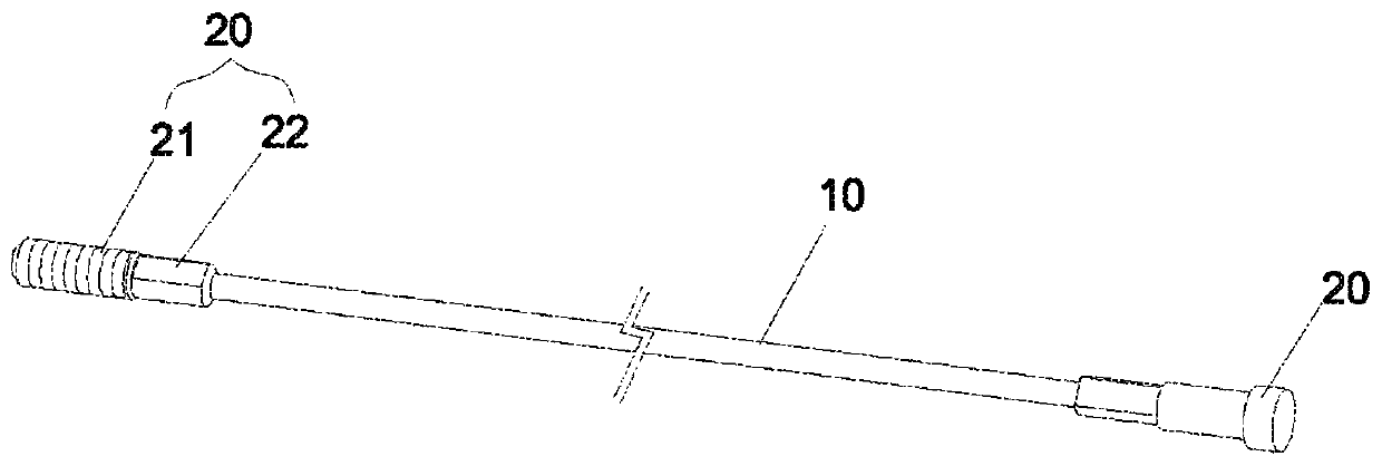
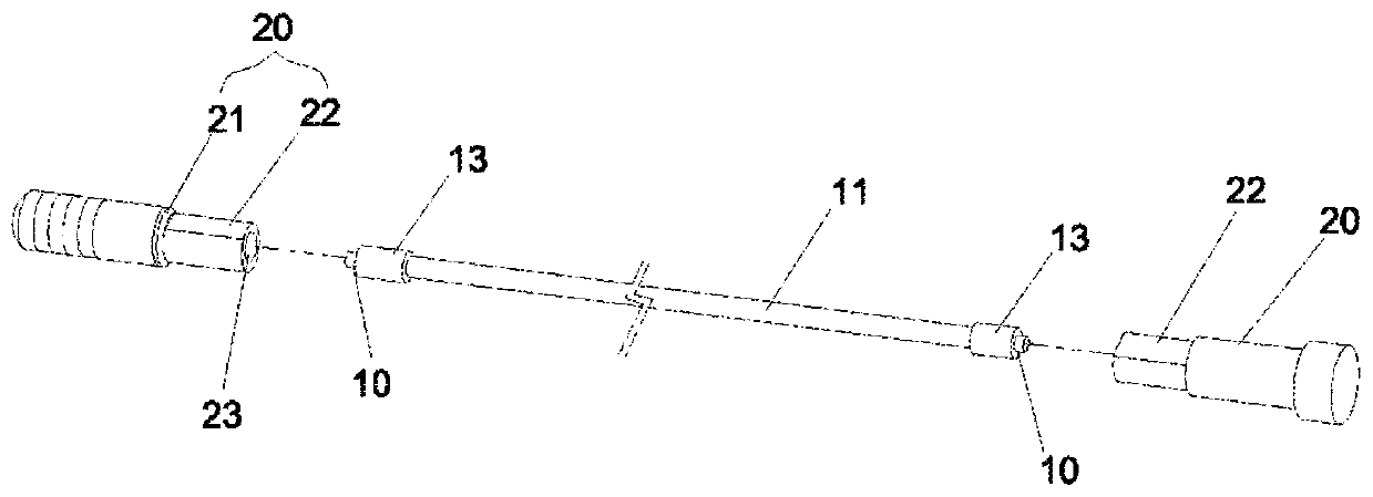
[0012] Please refer to Figure 1 to Figure 3 . like Figures 1 to 3 As shown, the bearing cable structure when manufacturing panels of the present invention may include steel cables 10 and two sets of fixing members 20 .

[0013] An outer layer 11 made of resin covers the steel cable 10 .

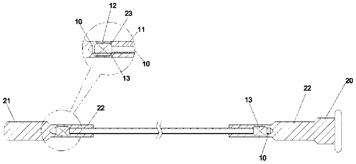
[0014] Two connecting portions 12 are respectively formed at both ends of the steel cable 10 not covered by the outer layer 11 . A non-slip ring 13 covers each of the two connecting parts 12 for fixing. The diameter of the anti-slip ring 13 is larger than that of the outer layer 11 . Alternatively, the steel cable 10 may be composed of multiple steel wires that are twisted around each other to form a biaxial structure or a single steel wire. shaft structure.

[0015] A threaded portion 22 is arranged on the outer edge of each fi...


PUM


Abstract

The invention discloses a bearing cable structure used during manufacturing for a panel. The bearing cable structure comprises a steel cable and two groups of fixing members. Each connection part of the steel cable is assembled onto a corresponding anti-slide ring, then assembled into an axial blind hole of each fixing member, and further connected to a screwing part of each fixing member in a riveting manner through a machine, so that the fixing members are closely connected to an outer cable layer, and the cable is mutually integrated with the fixing members to be prevented from separating off; and meanwhile, the riveting connection for the axial blind holes is capable of being combined with the outer layer, and double location is executed, so that the axial tension intensity of the bearing cable structure is increased, and the service life is prolonged.

Description

technical field [0001] The present invention relates to a bearing cable structure in the manufacture of a panel, and more particularly to a bearing cable structure capable of pulling the panel laterally during manufacture to make it structurally better and enhance axial tension to prevent displacement or sliding. [0002] technical background [0003] A conventional panel support structure, a rectangular frame is formed by a pair of pillars and a plurality of coupling beams spaced apart in the longitudinal direction of the rectangular frame and arranged therebetween. And, the rectangular frame is formed by a plurality of coupling beams adjacent to the rectangular frame in the depth direction of the rectangular frame. In addition, in the rectangular frame between the pair of uprights, a plurality of linear substrate support members arranged at intervals in the height direction at the same time, in the adjacent rectangular frame, are formed so that the same linear substrate sup...

Claims


Application Information

Patent Timeline
IPC IPC(8): F16C41/00F16C1/00
CPCF16C1/00F16C41/00
Inventor 张卉彭丹
Owner BEIJING XINLI MACHINERY
Why Eureka
Try Eureka