Monitoring camera mounting bracket convenient to adjust

A technology for monitoring cameras and installing brackets, which is applied in the direction of machine tables/brackets, supporting machines, mechanical equipment, etc., which can solve the problems of inconvenient angle and position adjustment, inconvenient camera loading and unloading, and difficulty in meeting people's daily needs, so as to solve the problem of angle and position Inconvenient to adjust, easy to replace and easy to install

Inactive Publication Date: 2020-06-19
刘维宏
View PDF0 Cites 20 Cited by
  • Summary
  • Abstract
  • Description
  • Claims
  • Application Information

AI Technical Summary

Problems solved by technology

[0003] Surveillance cameras are usually installed on brackets. The angle and position of the existing camera mounting brackets are inconvenient to adjust, and it is inconvenient to install and disassemble the cameras. It is difficult to meet people's daily needs.

Method used


Image

  • Monitoring camera mounting bracket convenient to adjust
  • Monitoring camera mounting bracket convenient to adjust
  • Monitoring camera mounting bracket convenient to adjust

Examples


Embodiment 1

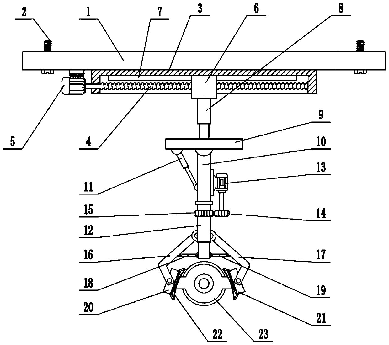
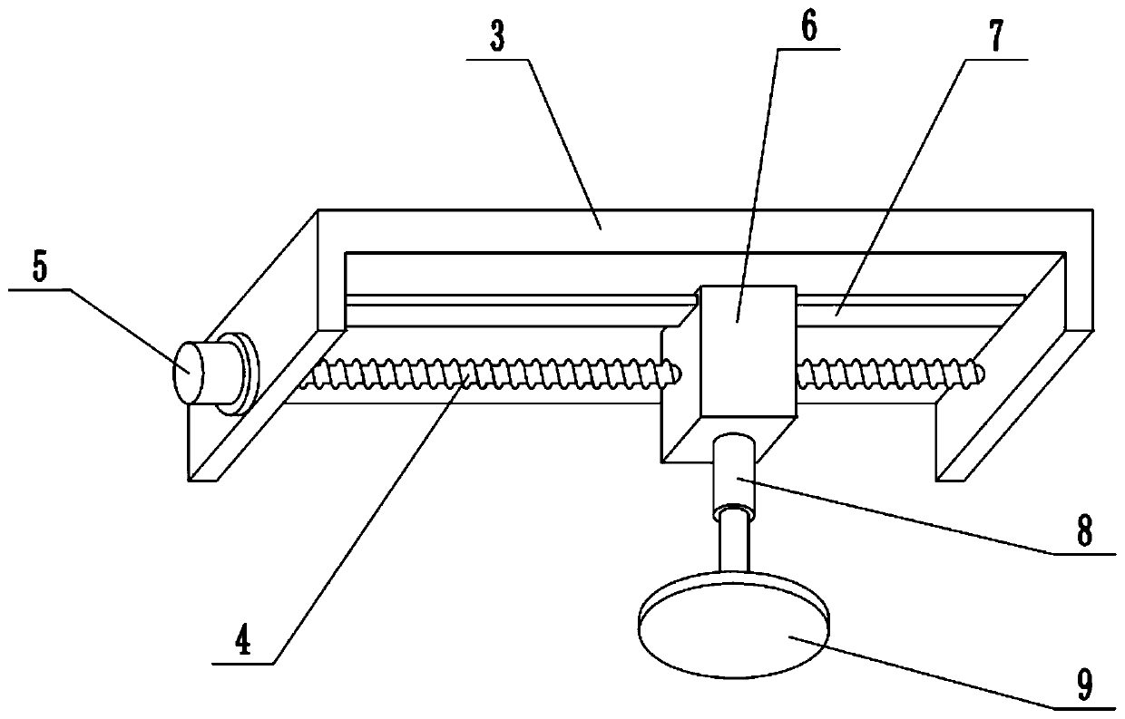
[0023] see Figure 1-3 , in the embodiment of the present invention, a monitoring camera mounting bracket that is easy to adjust includes a mounting plate 1, a fixing bolt 2, a fixing frame 3 and a camera 23, the mounting plate 1 is fixed on the ceiling by the fixing bolt 2, and the lower part of the mounting plate 1 The surface is fixedly connected with a fixed frame 3, and the inside of the fixed frame 3 is equipped with a screw rod 4, and the left and right ends of the screw rod 4 are respectively connected to the side walls of the fixed frame 3 for rotation, and the outer wall of the fixed frame 3 is fixedly connected with the first motor 5 , the first motor 5 is a forward and reverse motor, the middle part of the screw rod 4 is provided with a slider 6, the slider 6 is screwed to the screw rod 4, the top of the fixed frame 3 is equipped with a slide rail 7, and the top of the slider 6 is embedded Inside the slide rail 7, the slide block 6 is slidably connected with the sl...

Embodiment 2

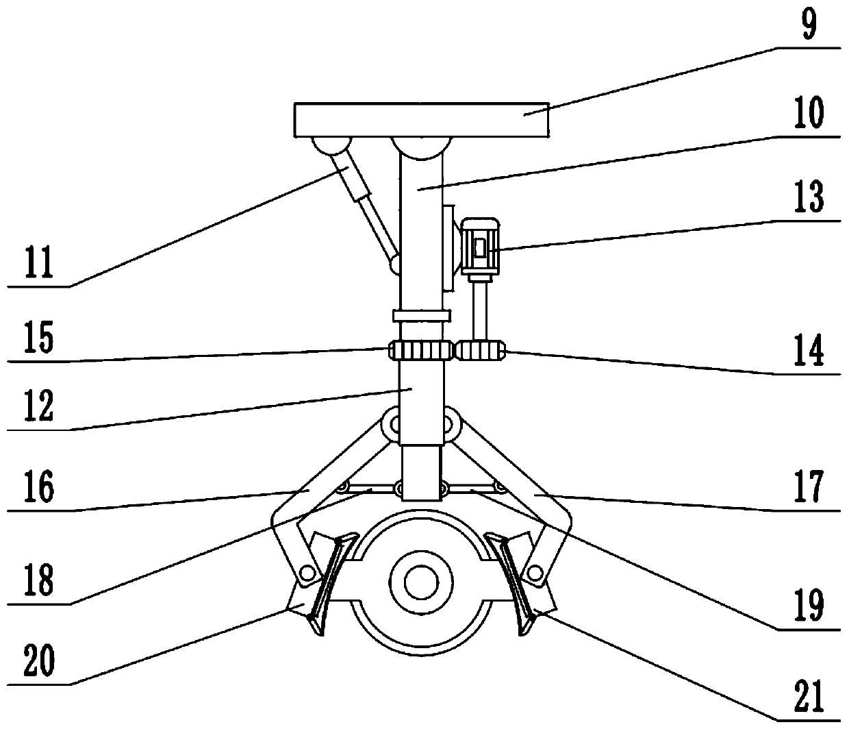
[0025] On the basis of Embodiment 1, the side wall of the swing rod 10 is fixedly connected with the second motor 13, the second motor 13 is a forward and reverse motor, the shaft extension end of the second motor 13 is provided with a driving gear 14, and the third telescopic A driven gear 15 is set on the mechanism 12, and the driving gear 14 meshes with the driven gear 15 to control the positive and negative rotation of the second motor 13, which can drive the positive and negative rotation of the driving gear 14, thereby driving the third telescopic mechanism through the driven gear 15 12 is reversed, thereby driving the camera 23 to rotate, thereby adjusting the angle of the camera 23 according to actual needs.

Embodiment 1、 Embodiment 2

[0026] In conjunction with Embodiment 1 and Embodiment 2, the working principle of the present invention is: the camera 23 is placed between the left clamping plate 20 and the right clamping plate 21, the third telescopic mechanism 12 is controlled to shorten, and the left connecting rod 18, the right The connecting rod 19 drives the left clamping arm 16 and the right clamping arm 17 respectively, so that the camera 23 is clamped by the left clamping plate 20 and the right clamping plate 21, so that the camera 23 remains fixed, and the installation is very convenient for replacement and maintenance The camera 23, during the working process, the camera 23 controls the forward and reverse rotation of the second motor 13, which can drive the driving gear 14 forward and reverse, thereby driving the third telescopic mechanism 12 forward and reverse through the driven gear 15, thereby driving the camera 23 to rotate, Thereby, according to actual needs, adjust the angle of camera 23, ...


PUM


Abstract

The invention relates to the technical field of monitoring, in particular to a monitoring camera mounting bracket convenient to adjust. The bracket comprises a mounting plate, a fixing bolt, a fixingframe and a camera, wherein the lower surface of the mounting plate is fixedly connected with the fixing frame, a lead screw is mounted inside the fixing frame, a first motor is fixedly connected to the outer side wall of the fixing frame, the middle of the lead screw is sleeved with a sliding block, the lower surface of the sliding block is fixedly connected with a first telescopic mechanism, thelower end of the first telescopic mechanism is fixedly connected with a lifting plate, a swing rod is installed on the lower surface of the lifting plate, a third telescopic mechanism is installed atthe lower end of the swing rod and rotationally connected with the swing rod, a left clamping arm and a right clamping arm are installed on the left side and the right side of the third telescopic mechanism respectively, and the camera is clamped through a left clamping plate and a right clamping plate, so that the camera is kept fixed, mounting is quite convenient, the camera is convenient to replace and maintain, and the angle of the camera can be conveniently and rapidly adjusted in the working process of the camera.

Description

technical field [0001] The invention relates to the technical field of monitoring, more specifically, a monitoring camera mounting bracket that is easy to adjust. Background technique [0002] Surveillance camera is a semiconductor imaging device, which has the advantages of high sensitivity, anti-glare, small distortion, small size, long life, and anti-vibration. Surveillance camera security system. [0003] Surveillance cameras are usually installed on brackets, and the existing camera installation brackets are inconvenient to adjust the angle and position, and the camera is inconvenient to install and disassemble, which is difficult to meet people's daily needs. Contents of the invention [0004] The object of the present invention is to provide an easily adjustable surveillance camera mounting bracket to solve the problems raised in the above-mentioned background technology. [0005] To achieve the above object, the present invention provides the following technical ...

Claims


Application Information

Patent Timeline
Patent Type & Authority Applications(China)
IPC IPC(8): F16M13/02F16M11/04F16M11/08F16M11/10F16M11/18
CPCF16M11/04F16M11/045F16M11/046F16M11/08F16M11/10F16M11/18F16M13/02
Inventor 刘维宏
Owner 刘维宏
Why Eureka
Try Eureka