Heat exchanger for motor vehicle and corresponding production method

A technology for heat exchangers and motor vehicles, used in heat exchanger fixing, heat exchange equipment, vehicle components, etc., can solve problems such as unreliable welding, cannot be on the bottom side, and no reliable welding, and achieve increased manufacturing tolerances, Improve quality and improve the effect of micro teeth

Active Publication Date: 2020-06-19
MAHLE INT GMBH
View PDF6 Cites 0 Cited by
  • Summary
  • Abstract
  • Description
  • Claims
  • Application Information

AI Technical Summary

Problems solved by technology

[0003] A disadvantage of the heat exchangers known from the prior art is that the welding of the sides can only be carried out on the front side of the bottom of each tube and not on its bottom side. , since the sides are only fixed in one direction during

Method used


Image

  • Heat exchanger for motor vehicle and corresponding production method
  • Heat exchanger for motor vehicle and corresponding production method
  • Heat exchanger for motor vehicle and corresponding production method

Examples


Embodiment Construction

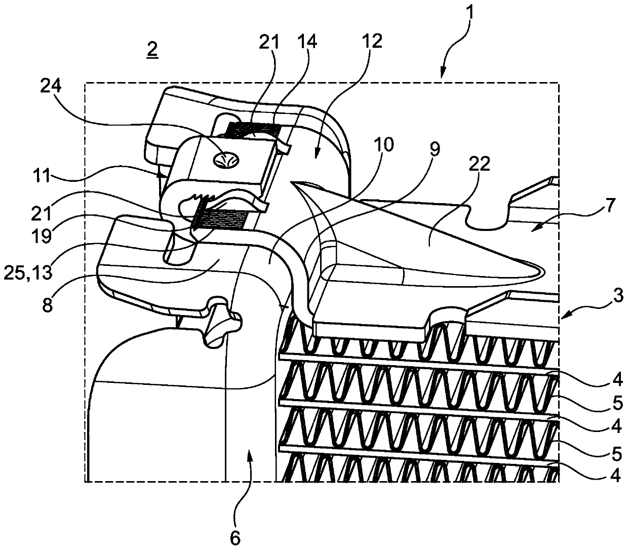
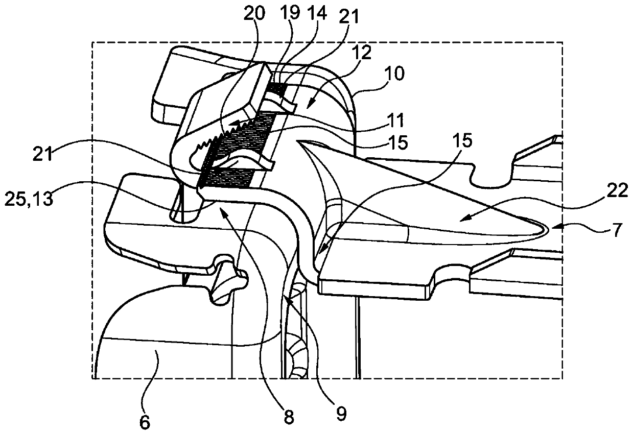
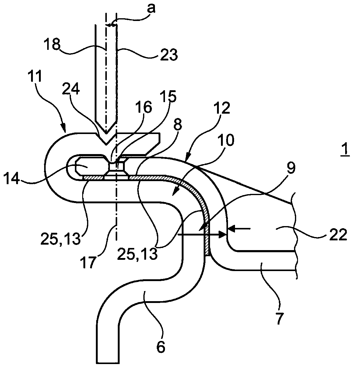
[0019] according to figure 1 , the heat exchanger 1 according to the invention for a motor vehicle 2 has a heat exchanger block 3 with a plurality of parallel flat tubes 4 through which a fluid can flow and a heat exchanger structure arranged therebetween 5, such as corrugated fins. The flat tubes 4 are here tightly accommodated at the longitudinal end sides in the respective associated tube bottom 6 , in particular in passages not shown in the insertion tube bottom 6 , and are tightly welded therein. The heat exchanger block 3 is closed on both sides by a side 7 (see also figure 2 and image 3 ), wherein the respective side portion 7 is mechanically and materially connected to the tube bottom 6 via a welded connection. According to the invention, the tube bottom 6 now has a front side 8 and a bottom side 9 which meet one another via a rounded corner region 10 . The tube bottom 6 has a deformable hook 11 on its front side 8 . The side part 7 has a web 12 on its longitudi...


PUM


Abstract

The invention relates to a heat exchanger for a method vehicle. The heat exchanger includes a heat exchanger block closed by a side part. Each side is mechanically and cohesively connected to the tubebottom via a welded connection. It is essential that the tube bottom has a front side and a bottom side that converge with each other via a circular corner region. A deformable hook is arranged on the front side of the tube bottom; the side part is provided with a connecting sheet on the longitudinal end side; the tabs are designed complementarily to the circular corner regions of the tube base,have sections abutting against the front side of the tube base and comprising through-holes or recesses, into which through-holes or recesses the material portions of the hooks are displaced by meansof punch holes, the axes of which are arranged offset parallel to each other, in the event that the heat exchanger has been assembled.

Description

technical field [0001] The invention relates to a heat exchanger for a motor vehicle according to the preamble of claim 1 . The invention also relates to a method for manufacturing a heat exchanger. Background technique [0002] In order to be able to meet the increasing stability requirements of modern heat exchangers, reliable and at the same time high-quality welds are required between the sides of the heat exchanger and the respective tube bottoms. In order to be able to ensure such a reliable weld, a reliable mechanical fixation of the individual sides to the associated tube bottom is indispensable and a contact surface as large as possible over which the welding is then performed is desired. [0003] A disadvantage of the heat exchangers known from the prior art is that the welding of the sides can only be performed on the front side of the individual tube bottoms, not on their bottom side, since the sides are only fixed in one direction during pre-assembly. This is ...

Claims


Application Information

Patent Timeline
IPC IPC(8): F28D21/00F28F9/18
CPCF28D21/00F28F9/18F28D2021/008B60H1/00328F28F2275/122F28F2275/14F28D1/05316F28F9/0219F28F9/165F28F9/182F28F2275/04B60H1/00321
Inventor 赖因哈德·海涅帕维尔·拉赫瓦尔斯基
Owner MAHLE INT GMBH
Why Eureka
Try Eureka